5
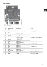
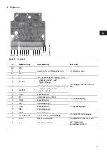
5. IO module
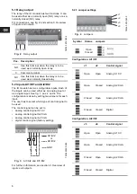
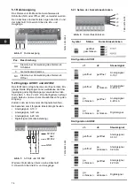
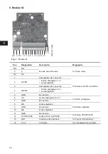
Fig. 1
IO module
TM
04
39
73
05
09
NO C
1 2 3 4 5 6 7 8 9 10 1112
NC
13 14
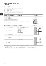
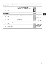
Pos.
Designation
Description
Section
NO
NO
Terminals for relay output
C
C
NC
NC
1
-
24 V supply for AI1
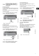
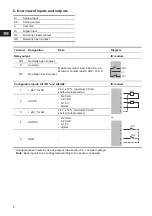
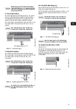
5.2 Inputs AI1/DI1 and AI2/DI2
2
AI1/DI1
• Analog input 1 or
• digital input 1
3
-
24 V supply for AI2
4
AI2/DI2
• Analog input 2 or
• digital input 2
5
GND
Earth terminal
6
AO
Analog output 0-10 V
7
GND
Earth terminal
8
DI3
Digital input 3
9
GND
Earth terminal
10
DI4
Digital input 4
11
GND
Earth terminal
12
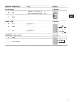
Pt100/Pt1000
Pt100 or Pt1000 input
13
LED
Power indicator
14
J1-J4
Jumpers


