6
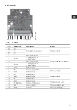
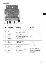
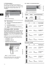
5.1 Relay output
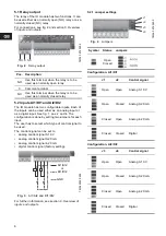
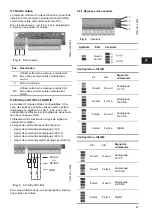
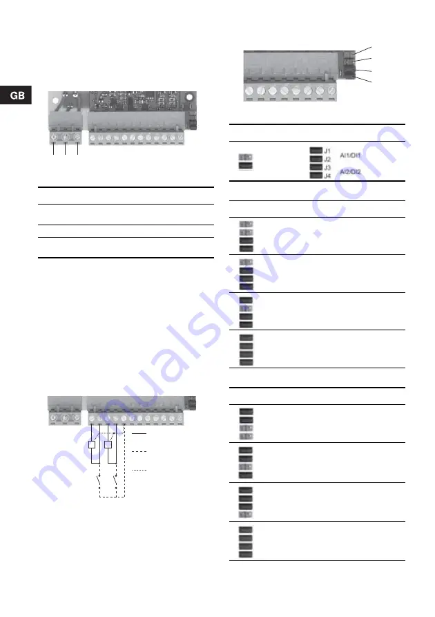
The relay of the IO module has two functions. It can
be used either as a normally open (NO) relay or as a
normally closed (NC) relay.
For connections, see fig. 2 and section 6. Overview
of inputs and outputs.
Fig. 2
Relay output
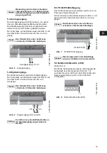
5.2 Inputs AI1/DI1 and AI2/DI2
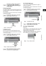
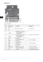
The IO module has two configurable inputs. Each of
the inputs can be used either as an analog input or
as a digital input. See fig. 1, pos. 2 and 4. The
configuration is done by setting two jumpers for each
input.
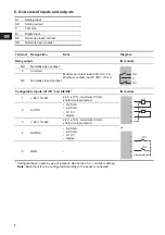
The user has to select which type of control signal to
be used.
The control signal can be set to
•
analog control signal 0-10 V
•
analog control signal 0-20 mA
•
analog control signal 4-20 mA
•
digital control signal (factory setting).
Fig. 3
AI1/AI2 and DI1/DI2
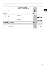
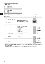
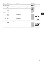
For further information, see section 6. Overview of
inputs and outputs.
5.2.1 Jumper settings
Fig. 4
Jumpers
Configuration, AI1/DI1
Configuration, AI2/DI2
TM
0
4
3
974
0
509
Pos.
Description
NO
Use this terminal when the relay is to be
used as a normally open relay.
C
Common terminal.
NC
Use this terminal when the relay is to be
used as a normally closed relay.
TM
04 403
2 050
9
NO C NC
AI1/AI2
DI1/DI2
or
GND
TM
04 39
75 050
9
Symbol
Status
Jumpers
Open
Closed
J1
J2 Control
signal
Open
Open
Analog 0-10 V
Open Closed
Analog
0-20
mA
Closed
Open
Analog 4-20 mA
Closed
Closed
Digital
J3
J4
Control signal
Open
Open
Analog 0-10 V
Open Closed
Analog
0-20
mA
Closed
Open
Analog 4-20 mA
Closed
Closed
Digital
J1
J2
J3
J4


