background image

16

11. Maintenance

The CU 361 is maintenance-free during normal use 
and operation. The CU 361 should be cleaned with 
a wet cloth.

12. Service

The CU 361 cannot be serviced. 

If the CU 361 is faulty, the unit must be replaced. 
See section 

13. Replacing the CU 361

13. Replacing the CU 361

1. Switch off the power supply to the CU 361.

2. Switch off the power supply to components with 

external supply.

3. Mark the individual conductors with the numbers 

of the corresponding terminals.

4. Disconnect all conductors.

5. Remove the CU 361 from the panel/cabinet.

6. Fit the new unit as described in section 

5. Mechanical installation

.

7. Configure the new CU 361 by means of 

a PC Tool.

13.1 Replacing the CIM module

1. Switch off the power supply to the CU 361.

2. Switch off the power supply to components with 

external supply.

3. Mark the individual conductors with the numbers 

of the corresponding terminals.

4. Remove the screws holding the CIM module.

5. Remove the CIM module from the CU 361.

6. Fit the new CIM module.

7. Connect the CIM module as described in the 

installation and operating instructions supplied 
with the new CIM module.

14. Dimensions

Fig. 17

Dimensional sketch

15. Disposal

This product or parts of it must be disposed of in 
an environmentally sound way:

1. Use the public or private waste collection service.

2. If this is not possible, contact the nearest 

Grundfos company or service workshop.

9

70

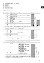
Relay 1

C

71

Relay 1

NO

72

Relay 1

NC

73

Relay 2

C

74

Relay 2

NO

75

Relay 2

NC

* GND is isolated from other ground connections.

Pos.

Terminal

Designation

Data

Diagram

74

73

72

70

71

75

TM

04

 20

68

 19

08

Subject to alterations.

Summary of Contents for CU 361

Page 1: ...4 Digital inputs 13 9 5 Analog inputs 13 9 6 Digital outputs relay outputs 13 9 7 Conductors 13 9 8 Battery backup UPS 14 9 9 Terminal groups 14 10 Overview of inputs and outputs 15 11 Maintenance 16...

Page 2: ...Description 1 LCD display 2 Changes to next column in menu structure 3 Changes to help text 4 Goes up in lists 5 Goes down in lists 6 Increases the value of a selected parameter 7 Reduces the value of...

Page 3: ...ear week 5 Rated voltage frequency and power TM04 2367 2408 TM00 5827 3408 Type Made in Thailand 96161750 Product No UN Serial No P c OPEN TYPE PROCESS CONTROL EQUIPMENT 100 240 Vac 50 60Hz Max 22W CU...

Page 4: ...ating 1 2 3 3R 5 12 12K or 13 4 3 Terminals All terminals are suitable for conductors of 0 5 to 2 5 mm2 or AWG 20 13 4 4 Cables Cables must be rated min 70 C 5 Mechanical installation Fasten the CU 36...

Page 5: ...e CIM module Fig 8 Screen fixed with cable clamp Signal conductors for digital and analog inputs and outputs should be screened i e run the screen all the way to the CU 361 and connect it to frame wit...

Page 6: ...s will be available in the future The CIM modules must be ordered separately The connection of the CIM module is described in the installation and operating instructions supplied with the module 6 3 F...

Page 7: ...upplied with the CIM module on the back cover See fig 13 Fig 13 Placing the new labels on the back cover 5 Refit the back cover to the CU 361 and secure it with the mounting screw See fig 14 Fig 14 Re...

Page 8: ...rcuit breakers must be done in accordance with local and national regulations 9 4 Digital inputs 9 5 Analog inputs 9 6 Digital outputs relay outputs 9 7 Conductors Warning Prior to start up read the i...

Page 9: ...e terminals of the groups 2 3 5 and 6 are insulated from all other terminal groups by reinforced insulation 2224 VAC All control terminals in groups 2 3 5 and 6 are supplied with SELV voltage Safety E...

Page 10: ...ut 11 GND 12 DI2 13 GND 14 DI3 All terminals except mains terminals must only be connected to voltages not exceeding 16 Vrms and 22 6 Vpeak or 35 VDC 6 Ethernet RJ45 External computing devices connect...

Page 11: ...ff the power supply to the CU 361 2 Switch off the power supply to components with external supply 3 Mark the individual conductors with the numbers of the corresponding terminals 4 Remove the screws...

Reviews: