2.1.2 Installation tips
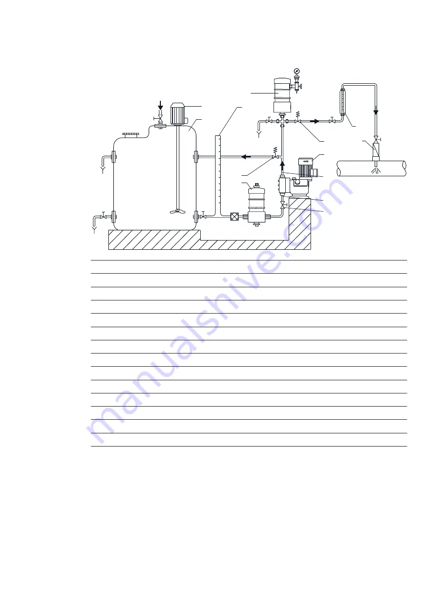
The drawing shows an example of an optimum installation. The following subsections describe
various components and when they should be used.
2
1
8
3
6
4
7
5
9
10
11
p1
p2
Pos.
Component
1
Dosing tank
2
Electric mixer
3
Graduated cylinder
4
Pulsation damper, inlet side
5
Dosing pump
6
Pressure relief valve
7
Pressure loading valve
8
Pulsation damper, outlet side
9
Measuring glass
10
Injection unit
11
Isolating valve
p1
Pressure at the inlet valve
p2
Pressure at the outlet valve
2.1.2.1 Installation with ball valve and non-return valve
For easy deaeration of the dosing head, we recommend that you install a ball valve (12) with a
bypass line immediately after the outlet valve.
In order to prevent backflow in the outlet line and to simplify startup, we recommend that you in-
stall a non-return valve (13) in the outlet line.
DMX 221 | |
7


