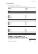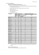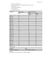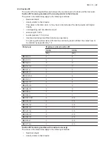
11.1.1 Function of the electronic unit for optical sensor
Relay outputs
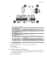
The electronic unit for optical sensor has two relay outputs:
•
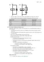
Relay 1 (C1): potential-loaded output, AC mains voltage, 230 V or 115 V, depending on the
model
C1 can be used to switch off the pump in case of a diaphragm leakage.
•
Relay 2 (C2): potential-free output
C2 can be used to trigger an alarm device in case of diaphragm leakage.
LEDs
The electronic unit for optical sensor has two LEDs.
•
Green LED:
•
The green LED indicates that the system is ready for operation.
•
The green LED is on when the sensor is connected to the electronic unit. If the LED is
off, the sensor is defective or wrongly connected.
•
The green LED stays on when the red LED is on.
•
Red LED:
•
The red LED indicates that a diaphragm leakage has been detected.
11.1.2 Mounting the electronic unit for optical sensor
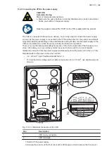
Have a screwdriver for the plastic screws in the cover of the electronic unit available. You also
need four 4.5 x 35 mm screws and a suitable screwdriver for fastening the unit to the wall. The
four screws are not included in the scope of delivery.
The diaphragm leakage sensor with electronic unit for optical sensor is supplied with a 5 m cable.
Mount the electronic unit on the wall close to the pump.
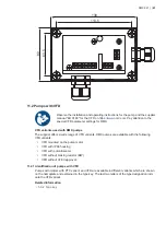
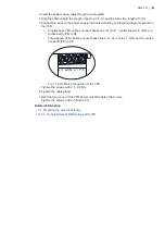
1. Drill four Ø6 holes according to the drilling scheme.
2. Unscrew the plastic screws in the cover of the electronic unit.
3. Remove the cover with the plastic screws from the electronic unit.
4. Mount the electronic unit on the wall by means of the four screws.
5. Tighten the screws gently in order not to damage the electronic unit.
6. Fit the cover to the electronic unit and fasten it with the plastic screws.
Related information
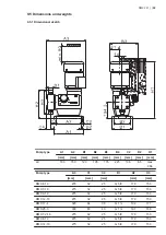
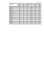
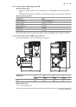
• 11.1.6.1 Dimensional sketch of the electronic unit for optical sensor
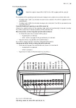
11.1.3 Electrical connection
DANGER
Electric shock
Death or serious personal injury
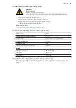
● All electrical connections must be carried out by qualified persons.
● Switch off the power supply before making any electrical connections.
•
Make sure the power supply specified on the nameplate matches the local conditions.
•
Provide relay outputs on site with appropriate backup fuses.
•
To ensure electromagnetic compatibility (EMC), the input cables and current output cables
must be screened.
•
Route input cables, current output cables and power supply cables in separate ducts.
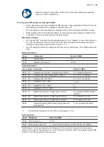
11.1.3.1 Connecting the diaphragm leakage sensor electrically with the AR control unit
If the pump is equipped with an AR control unit, the diaphragm leakage sensor has a 1 m cable
with an M12 plug.
Observe the installation and operating instructions for the AR control unit.
DMX 221 | |
56

