background image


16 | 

P a g e


INSTALLATION - BOOSTING: 


Using 1 Float Switch and 1 Pressure Switch


Start condition:


If the water level in source tank is high and the float switch A in the source 

tank is in up position and the Pressure in the line is below the cut-in pressure 

setting on the pressure switch A the pump starts. Panel will alternate between 

pump A and pump B, when previous demand cycle is completed, and pump(s) 

have stopped. LCD screen displays RUN indicating pump is running.


Stop condition:


If the water level in the source tank is low and Float switch A in the source tank 

is in down position, the pump stops. LCD screen displays NO WATER, that means 

there is no water in the source tank and can lead to a dry run situation.


If the Pressure in the line is equal to or above the cut-out pressure setting on 

the pressure switch A installed, the pump stops. LCD screen displays FULL, that 

means there is no demand of water.


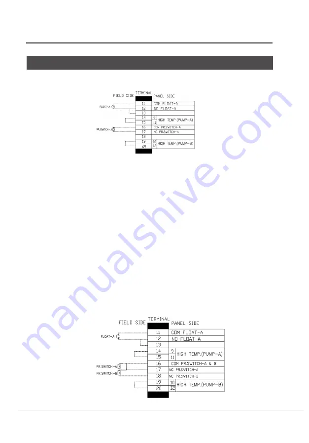
Using 1 Float Switch and 2 Pressure Switch


TERMINALS


Summary of Contents for DPC 2-1

Page 1: ...1 P a g e DPC 2 1 Installation and Operating Instructions DPC 2 1 For Single Phase Pumps up to 15A ...

Page 2: ...tions 13 Installation Boosting 16 Terminals 17 DIP Switch Settings 18 Electrical Connections 19 Installation Water Transfer 20 Terminals 21 DIP Switch Settings 22 Electrical Connections 23 OPERATION 24 Parameter Calibration 24 Erasing Former Parameters 25 Erasing TheParameter Calibration 25 Switching to AUTO mode 25 Switching to MANUAL mode 25 Pump Protection 25 Last Five Failure Records 26 Pump A...

Page 3: ......

Page 4: ...s the right to make any modifications to this product from time to time SAFETY WARNING If these safety instructions are not observed it may result in malfunction or damage to the equipment All electrical connections must be carried out by skilled and qualified personnel Never connect AC power to output L1 N1 L2 N2 terminals Ensure the motor controller and power specifications are matching CAUTION ...

Page 5: ...ere is a need to control and protect two pump installations and managing the automatic operation by a variety of switching methods Typical applications Water supply Irrigation Sewage Booster sets Rainwater reuse Stormwater FEATURES Built in function switch for Drainage by liquid level control through float switches Boosting water supply by pressure control through pressure switch and tank Transfer...

Page 6: ...s than 5 sec Trip response time of dry run 6 sec or this can be set manually Recovery time of overload 30 min or this can be set manually Recovery time of under over voltage 5 min Recovery time of dry run 30 min or this can be set manually Trip voltage of over voltage 115 of rated input voltage Trip voltage of under voltage 80 of rated input voltage PROTECTIONS COVERED Dry run without float probe ...

Page 7: ...eyond the scope of the company s quality guarantee TOOLS USED IN CONTROLLER INSTALLATION Controller installation and wire installation will need the following tools you also can choose the right tools according to your own experience Back view Side view wall Mounting clamp CONTROLLER COMPONENTS Voltage Displaying Area Ampere Displaying Area Fault Displaying Area Pump RunningStatus Displaying Area ...

Page 8: ... eg pump dry run trip time units seconds Pump fault icon when this icon appears it means controller is displaying some fault condition Network connection error icon when this icon appears it means there is no network connection or network connection error between pump controller and computer SCADA BMS Network normal connection icon when this icon appears it means the network connection between pum...

Page 9: ... Second S H Hour Ampere A Percent Pump running Pump stopped Low pressure or lack of pressure in the pipeline or pressure tank High pressure or full of pressure in the pipeline or pressure tank Pump A A B Pump B ...

Page 10: ...10 P a g e POWER TERMINAL CONNECTIONS Single Phase without running capacitor Single Phase with running capacitor ...

Page 11: ...Float A is in up position Panel will start pump A Panel will alternate between pump A and pump B after previous cycle is completed LCD screen will display RUN whichever pump in running Stop condition If the liquid level in the pit tank falls ie Float A is in down position Panel will stop whichever pump is running This means that there is not enough water to pump LCD screen will display No water TE...

Page 12: ...As soon as Float switch B reaches up position panel will start whichever pump is in standby E g If pump A was running and liquid level rose even further and Float B comes in up position pump B will also start operating in parallel to pump A Stop condition If the liquid level in the pit tank falls i e Float A is in down position Panel will stop whichever pump is running This means that there is not...

Page 13: ...ing an overflow alarm will generate an audio visual sound with fault indica tion on LCD screen showing Overflow This fault will reset itself only when liquid level in pit tank falls below Float C and Float C is in down position Stop condition If the liquid level in the pit tank falls ie Float A is in down position Panel will stop whichever pump is running This means that there is not enough water ...

Page 14: ...een Drainage Setting Switches Down Drainage Symbol Pump connection for over temperature protection where supplied with pump Pump Shell 19 20 Jumpers Lead Pump Shell Over Temperature Thermal Switch Pump A PumpB Over Temperature Thermal Switch DIP SWITCH SETTINGS NOTE To enable the pump s over temperature protection connect the pump s thermistor leads to terminals 14 and 15 19 and 20 and remove the ...

Page 15: ...15 P a g e Meanings of the messages graphic shown on the LCD screen Messages Graphics No water Description Lack of water in sump Overflow Overflow in sump ...

Page 16: ...s completed and pump s have stopped LCD screen displays RUN indicating pump is running Stop condition If the water level in the source tank is low and Float switch A in the source tank is in down position the pump stops LCD screen displays NO WATER that means there is no water in the source tank and can lead to a dry run situation If the Pressure in the line is equal to or above the cut out pressu...

Page 17: ...dition to operating pump Both pumps will run simultaneously in parallel operation Note Cut in pressure of Pressure switch B Cut in pressure of Pressure switch A Stop condition If the water level in the source tank is low and Float switch A in the source tank is in down position the pump s stops LCD screen displays NO WATER that means there is no water in the source tank and can lead to a dry run s...

Page 18: ...mbol Boosting Setting SwitchesUP Boosting Symbol DANGER Electric shock risk Before carrying out any installation or maintenance operation the controller should be disconnected from the power supply and the person should wait at least 2 minutes before opening the controller Never connect AC power to output L1 N1 L2 N2 terminals Ensure the motor controller and power specifications match The electric...

Page 19: ...on Low water level in source tank Enough water in source tank High pressure in pipeline or pressure tank Low pressurein pipeline or pressure tank NOTE To enable the pump s over temperature protection connect the pump s thermistor leads to terminals 14 and 15 19 and 20 and remove the jumper If the pump is without thermistor switch please use jumper to connect terminals 14 and 15 19 and 20 NOTE Pres...

Page 20: ...s completed LCD screen will display pump A B run on screen Stop condition If the water level in UG tank is low ie Float A is down if any of the pump s are running panel will stop the pump s indicating that there is not enough water in UG tank LCD screen will display No water If the water level in OH tank is high ie Float A is up Panel will stop the pump s that are running indicating that the OH ta...

Page 21: ......

Page 22: ...H tank has gone even more down due to rising demand and Float C is also now in down position panel will start pump B also Stop condition If the water level in UG tank is low ie Float A is down if any of the pump s are running panel will stop the pump s indicating that there is not enough water in UG tank LCD screen will display No water If the water level in OH tank is high ie Float A is up Panel ...

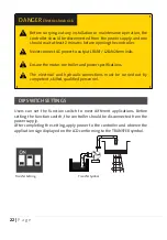
Page 23: ...the TRANSFER symbol Transfer Setting Transfer Symbol DANGER Electric shock risk Before carrying out any installation or maintenance operation the controller should be disconnected from the power supply and one should wait at least 2 minutes before opening the controller Never connect AC power to output L1 N1 L2 N2 terminals Ensure the motor controller and power specifications The electrical and hy...

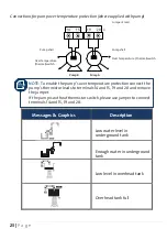
Page 24: ...witch Messages Graphics Description Low water level in underground tank Enough water in underground tank Low level in overhead tank Overhead tank full NOTE To enable the pump s over temperature protection connect the pump s thermistor leads to terminals 14 and 15 19 and 20 and remove the jumper If the pump is without thermistor switch please use jumper to connect terminals 14 and 15 19 and 20 19 2...

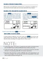
Page 25: ... switched from Auto to Manual Make sure that the pump is not running and LCD screen is displaying 2 Press the A START key to run pump A confirm the pump and all pipe network is in normal working state including voltage amps etc with LCD screen displaying 3 Press and hold the START key and release when the countdown starts The controller makes a beep and a countdown starts with the LCD displaying C...

Page 26: ... flashing will appear in the LCD displays Repeat for pump B by using the B STOP key for 3 seconds SWITCHING TO AUTO MODE To switch between MANUAL and AUTO mode press MODE key AUTO mode automatically locks controller Under AUTO mode the controller will run or stop the pump according to the signal from the float switch NOTE Under AUTO mode if the pump is running and user wants to stop the pump press...

Page 27: ...er a built in time delay has elapsed The controller will not recover automatically until all the abnormal situations have been cleared If pump stalled open phase or other serious failure has occurred pump user must immediately check pump and motor LAST FIVE FAILURE RECORD The control panel can memorize the last five failures of pump so it is very convenient for the users to analyze the pump runnin...

Page 28: ...sure that the pump is not running and the LCD screen is displaying 2 Press and hold the STORE key and A STOP key The controller makes a beep sound and displays the accumulative run time The pump has run for 23 hours 3 Press the A STOP key to quit the accumulative running time display 4 Repeat for pump B by using B STOP key NOTE The failure displayed above is PUMP STALLED Repeat for pump B by using...

Page 29: ...m BASIC FUNCTION Computer SCADA BMS Optional with communication interface can realize long distance monitoring In the control room users can realize all the functions of the master controller through the slave controller except parameter calibration and adjusting SPECIAL APPLICATION As adopting communication interface the communication distance through wire is less than 1200 meters whereas for a l...

Page 30: ...it 8 data bit 1 stop bit no verify Baud rate 1200 2400 4800 9600 bps default 9600bps Setting range of controller address 1 126 127 broadcast address host computer broadcasting slave machine response forbidden Protocol type MODBUS protocol RTU Rated input voltage for SC AC 240V 50Hz single phase Main Installation Data Wire communication distance 1200 meters max by shield twisted pair cable STP for ...

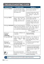
Page 31: ... to restart the pump every 30 min until running ampere is restored to normal Inspect pump and motor winding Flashing of PUMP NO CALIBRATION Parameter calibration not completed Refer to parameter calibration setting Flashing of DRY RUN Liquid level in the well sump is below the pump intake pump stops running Controller will attempt to restart the pump every 30 min until liquid level is above the pu...

Page 32: ...The name Grundfos the Grundfos logo and be think innovate are registered trademarks owned by Grundfos Holding A S or Grundfos A S Denmark All rights reserved worldwide Version 02 0522 ...

Reviews: