Monitoring Unit – GU02
Prepared by.
Rev. No.
Rev1.0
Date.
12-Nov-13
Page.
4 / 7
⑧
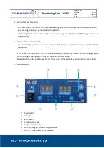
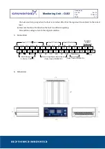
Phase indication lamp for stator windings; R for U, S for V, T for W
⑨
Bearing indication lamp: H for upper bearing, L for lower bearing
⑩
Status indication lamp
4.
Operating & Setup Sequence
GU02 unit is installed in the MCC(motor control center) and accordingly MCC manufacturer should prepare
the wiring in the panel for GU02 accordingly.
Therefore if the panel is not supply scope of Grundfos, it is strongly recommended to supply GU02 unit to
the selected MCC manufacturer.
The GU02 unit is sophisticated and sensitive instrument with many useful functions. It should be handled
the correct ways and connected in accordance with the instructions.
Please follow the below procedure to set up GU02.
1)
First of all, check the input voltage to GU02 whether it is in the range of AC 90 ~ 240VAC, 50/60Hz,
6W Max.
2)
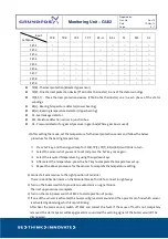
Follow the below procedure to set the parameters of operation.
①
Turn on the power switch of GU02.
②
Wait to disappear the value of basic SET Number on display window.
③
Press the 'Set' button for 5 seconds when the basic SET Number disappears. The basic SET Number
will be displayed on the left display window again.
④
Select new Set Numbers by using up/down key
⑤
Press the “SET” button.
⑥
Show “Cht_” (C with one digit number) on the screen.
⑦
Select the “Cht_” by using up/down key
⑧
Press the “SET” button and the set up procedure is complete.
* Remarks
The "C_" settings are a timing mechanism. The C1 means the thermals in each phase are checked separately
In every one second, C2 means every two seconds, C3 means every three seconds, etc.

