33
English (US)
Warning (only three-phase pumps)
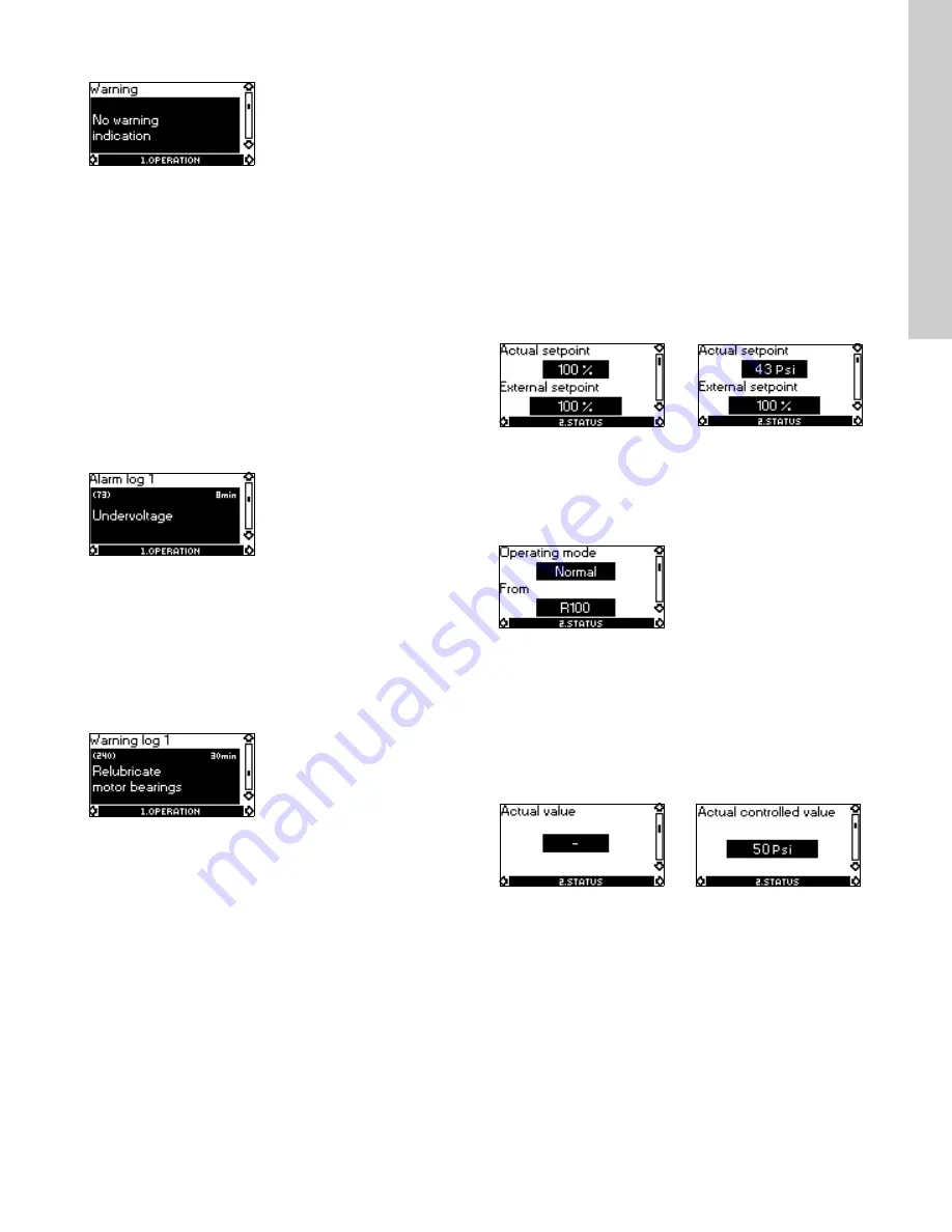
In case of warning, the cause will appear in this display.
Possible causes:
• No warning indication.
• Sensor signal outside signal range.
• Relubricate motor bearings, see section
27.2 Relubrication of
motor bearings
.
• Replace motor bearings, see section
27.3 Replacement of
motor bearings
.
• Replace varistor, see section
27.4 Replacement of varistor
(only 15-30 hp)
.
A warning indication will disappear automatically once the fault
has been remedied.
17.1.4 Fault log
For both fault types, alarm and warning, the R100 has a log
function.
Alarm log
In case of "alarm" faults, the last five alarm indications will appear
in the alarm log. "Alarm log 1" shows the latest fault, "Alarm log 2"
shows the latest fault but one, etc.
The example above gives this information:
• the alarm indication Undervoltage
• the fault code (73)
• the number of minutes the pump has been connected to the
power supply after the fault occurred, 8 min.
Warning log
In case of "warning" faults, the last five warning indications will
appear in the warning log. "Warning log 1" shows the latest fault,
"Warning log 2" shows the latest fault but one, etc.
The example above gives this information:
• the warning indication Relubricate motor bearings
• the fault code (240)
• the number of minutes the pump has been connected to the
power supply since the fault occurred, 30 min.
17.2 Menu STATUS
The displays appearing in this menu are status displays only. It is
not possible to change or set values.
The displayed values are the values that applied when the last
communication between the pump and the R100 took place. If a
status value is to be updated, point the R100 at the control panel
and press "OK". If a parameter, e.g. speed, should be called up
continuously, press "OK" constantly during the period in which the
parameter in question should be monitored.
The tolerance of the displayed value is stated under each display.
The tolerances are stated as a guide in % of the maximum values
of the parameters.
17.2.1 Actual setpoint
This display shows the actual setpoint and the external setpoint in
% of the range from minimum value to the setpoint set. See
section
21. External setpoint signal
.
17.2.2 Operating mode
This display shows the actual operating mode (Normal (duty),
Stop, Min., or Max.). Furthermore, it shows where this operating
mode was selected (R100, Pump, Bus, External or Stop func.).
For further details about the stop function (Stop func.), see
section
17.3.8 Stop function
.
17.2.3 Actual value
This display shows the value actually measured by a connected
sensor.
If no sensor is connected to the pump, "-" will appear in the
display.
Without sensor
(uncontrolled)
With pressure sensor
(controlled)
Tolerance: ± 2 %.
Tolerance: ± 2 %.
Without sensor
(uncontrolled)
With pressure sensor
(controlled)


