

GRuNDFOS
Oxiperm batch mOde
QUICK REFERENCE GUIDE
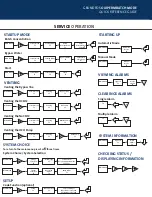
SERVICE
OPERATION
STARTUP MODE
STARTING UP
VENTI
NG
manual mode
automatic mode
CLEARINGS ALARMS
Single alarm
F4
multiple alarm
F4
VIEWING ALARMS
Main Menu
Logbook
F3
Active
alarms
F2
Main Menu
Main Menu
Automatic
Mode
F1
Manual
Mode
F2
Main Menu
batch concentration
bypass Water
Start
Main Menu
Main Menu
Service Mode
F3
Service Mode
F3
ServiceMode
F3
Startup Mode
F2
Startup Mode
F2
Startup Mode
F2
Batch
Concentration
F1
Bypass Water
F2
Start?
F3
Enter
Concentration
F1=>
Enter Limit
F1=> . F1
Venting the bypass line
Venting the hc1O2
Venting the Nac1O2
Venting the h2O pump
Main Menu
Main Menu
Main Menu
Main Menu
Service Mode
F3
Service Mode
F3
Service Mode
F3
Service Mode
F3
Venting
F1
Venting
F1
Venting
F1
Venting
F1
Bypass Line
F1
HC1 Pump
F2
NaC1O2 Pump
F3
H2O Pump
F1
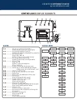
SYSTEM INFORMATION
CHECKING STATUS /
DISPLAYING INFORMATION
Main Menu
Main Menu
Logbook
F3
Active
alarms
F2
SYSTEM CHOICE
Main Menu
Main Menu
System choice / System Selection
to return to the main menu press esc three times.
Service
Selection
F1
System
Selection
F1
System Type
F1
Operating
Mode
F2
Select System
based on model number
F1,F2,F3 >
Batch Mode
F1
SETUP
code Function (optional)
Main Menu
Setup
F2
Code Function
F1
Select Privileges
Operation=>Level 1=0
Unlimited=>Level 2=0
L-DIS-SL-01.04-13.indd 2
4/11/2013 2:24:13 PM


