English (GB)
18
5.2.3 Checking the tightness of pressure gas lines
Pressure gas lines are all lines from the gas containers to the
vacuum regulator.
• If the plant is equipped with a nitrogen rinsing device:
Check tightness roughly with nitrogen.
• Detailed checking with amonia.
Checking the tightness with nitrogen
• Close all container valves
• Open container connection valves and all shut-off valves up to
the gas dosing system
• Open the connection valve of the nitrogen cylinder
• Slowly open the valve of the nitrogen cylinder, until the lines
have a pressure of about 10 bar (read at the manometer of
the vacuum regulator).
• Apply soap water to all components under pressure
– Formation of bubbles and/or pressure drop at manometer:
Leakage in pressure lines!
Depressurize the plant!
Eliminate leakage!
Check tightness again!
No formation of bubbles, pressure at manometer does not drop
significantly within one hour: Pressure lines are tight.
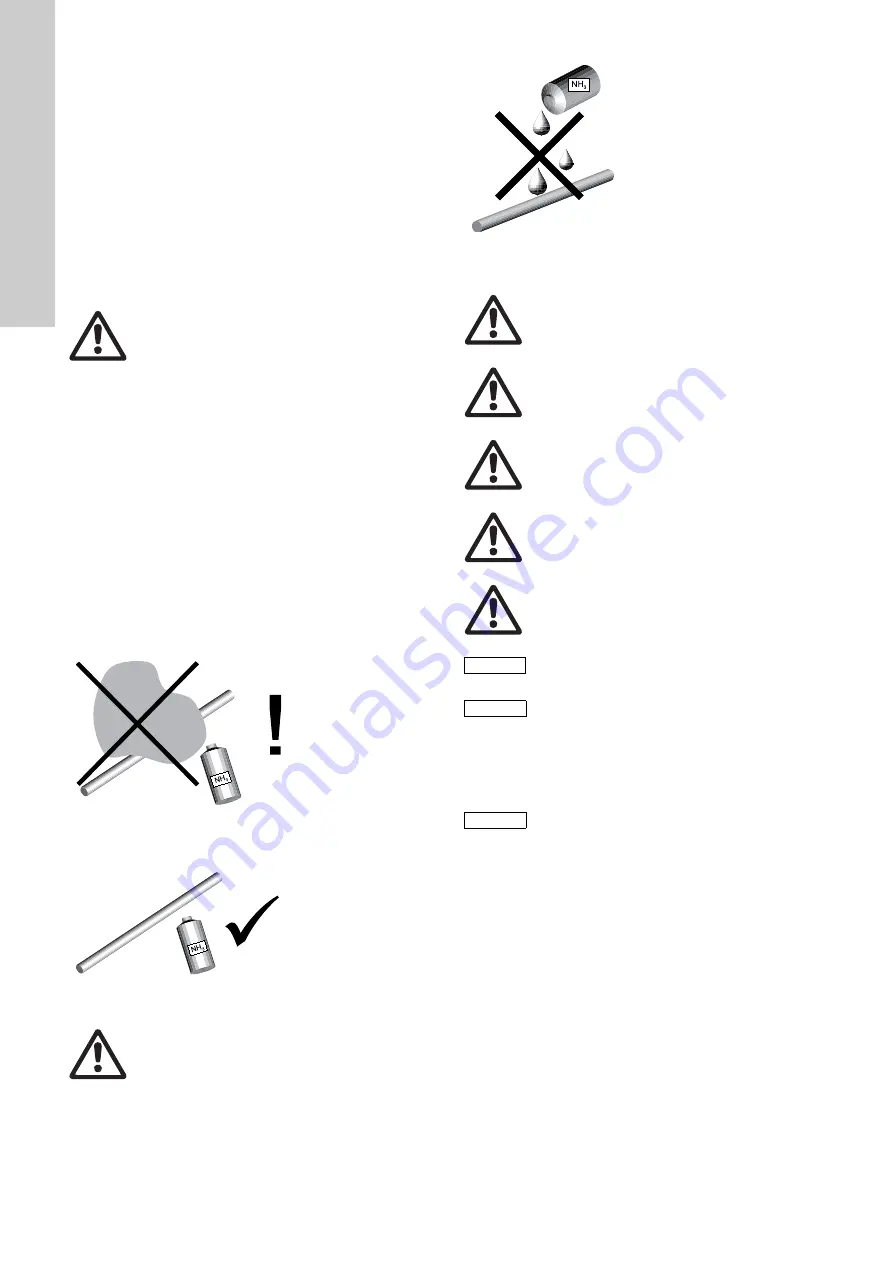
Checking the tightness with ammonia
• Open all container valves and container connection valves and
quickly close them again
• Slowly pass the open ammonia bottle along pressure-gas
leading parts
• Formation of white mist:
Leakage in pressure lines!
Depressurize the plant!
Eliminate leakage!
Check tightness again!
Fig. 27
Formation of white mist: Leakage in pressure lines!
– No formation of white mist: Pressure lines are tight.
Fig. 28
No formation of white mist
Fig. 29
Danger of leakages
5.2.4 Servomotor tests
5.2.5 Checking the servomotor's direction of rotation
The servomotor is controlled by an external controller. This
means that the servomotor's direction of rotation depends on the
controller's cabling and settings being correct.
Warning
Maximum nitrogen pressure 16 bar!
Danger of damages and chlorine break-out when
being exceeded!
T
M
04
08
49
09
08
T
M
04
06
97
09
08
Warning
Liquid ammonia must not come in contact with parts
of the plant!
Danger of leakages by corrosion!
T
M
04
06
98
09
08
Warning
The drive may only be commissioned if the hood and
cable entries are properly closed.
Warning
Please note that the process of commissioning the
drive will cause associated fittings/levers/rodding to
move.
Warning
Check that all the emergency equipment/functions on
your installation are working correctly.
Warning
Once all adjustment work has been completed,
check that the drive and the fittings/levers, etc.
operated by it are working correctly.
Warning
Never work with a damaged drive.
Caution
When commissioning, all the installation's
components must be ready for operation.
Note
Follow the installation and operating instructions for
the components used.
Note
Observe the installation and operating instructions
for the controller and the gas dosing system.


