background image

CD 21 / CD 22

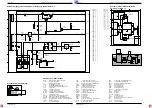
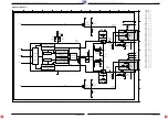
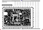
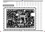
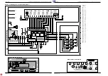
Schaltpläne und Druckplattenabbildungen / Circuit Diagrams and Layout of PCBs

CD 21 / CD 22

Schaltpläne und Druckplattenabbildungen / Circuit Diagrams and Layout of PCBs

GRUNDIG Service

GRUNDIG Service

2 - 5

2 - 6

MAINS V

O

LT

A

G

E

MC79L15

+VKK

-VKK

-

-

-

-

-

-

-

-

MC7805CT

-

-

-

-

-

-

-

-

-

VFTD

4

5

6

1

7

8

9

2

3

D

C

G

B

A

F

E

D

C

G

B

A

F

E

4

5

6

1

7

8

9

2

3

1510

T1A

1511

T1A

22n

2534

22n

2533

100n

2535

22n

2537

22n

2539

100n

2541

820R

3541

2K7

3542

22k

3544

4k7

3543

1k

3560

4k7

3563

4k7

3562

47k

3540

4R7

3545

1R

3565

1R

3564

KILLI

DISEN

KILL

+5

+5

+5

+10

-10

1N4148

6544

1N4002

6543

1N4148

6542

1N4002

6540

1N4002

6535

1N4002

6537

1N4002

6538

1N4002

6536

1N4002

6561

1N4002

6560

1

2

3

4

1507

1507

1507

1507

1076

1

1076

2

1076

3

1506

6

1506

5

1506

4

1506

2

1506

3

1506

1

1530

2542

1000u/10V

2536

3300u/16V

2538

2200u/16V

2540

220u/50V

2560

330u/16V

7541

BC548B

BC338

7542

7543

BC558B

7650

BC558B

6541

6V8

6562

3V9

7535

3

2

1

7540

3

1

2

1508

1508

1508

1508

4

3

2

1

5.6V~

26.5V~

10.2V~

10.2V~

0V

-33V

-6.8V

-15.5V

-16V

-22V

-20V

-17V

+10V

+5V

-10V

13V

3.9V

-

-

-10

HPR

GND

HPL

+10

-

-

-

-

-

(B)

(A)

NJM4556

NJM4556

10k

10k

1

2

3

A

D

C

B

A

D

C

B

1

2

3

1005

1

1005

2

1006

1

1006

2

1006

3

1006

4

1006

5

1371

R

L

22n

2373

1n

2372

1n

2371

22n

2370

120R

3386

120R

3375

15k

3373

10k

3377

10k

3372

15k

3374

3376

3376

7370

1

3

2

7

5

6

8

4

7370

0V

0V

0V

0V

0V

0V

7370

1371

2370

2

371

3375

3386

2372

3373

3377

9306

100

6

2373

9305

3376

3372

3374

1005

1

3

6

GN

D

L

R

1510

1507

1530

3564

1511

3565

3

6

1

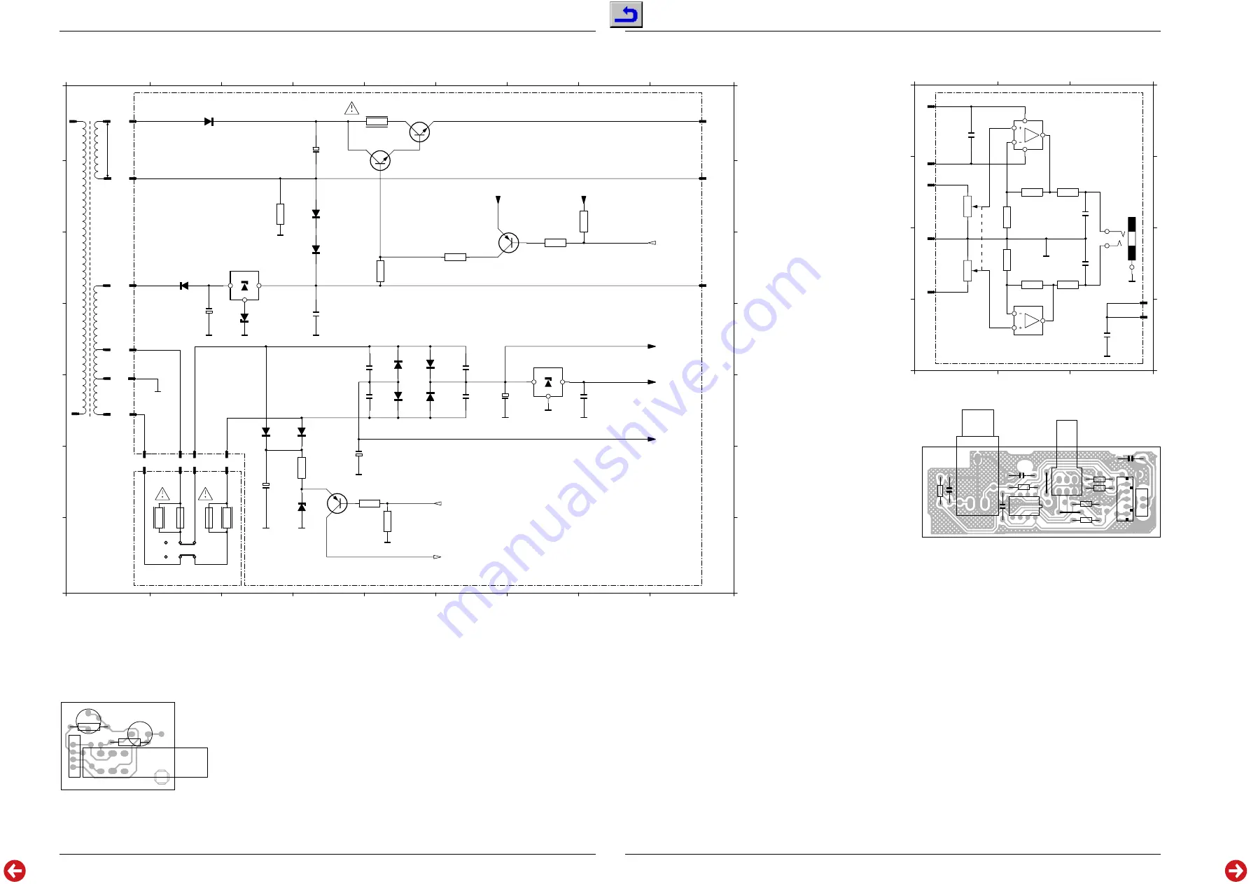
Stromversorgung und Schalterplatte / Power Supply and Switch Board

Schalter-Platte / Switch Board

Kopfhörer-Platte / Headphone Board
nur CD 22 / only CD 22

Bauteil

X

Y

Component

1076

A

9

1076

C

9

1076

B

9

1506

E

2

1506

E

1

1506

D

2

1506

C

2

1506

B

2

1506

A

2

1507

F

1

1507

F

2

1507

F

2

1507

F

3

1508

E

1

1508

E

2

1508

E

2

1508

E

3

1510

F

2

1511

F

2

1530

G

2

2533

E

6

2534

D

6

2535

E

8

2536

E

7

2537

D

5

2538

F

5

2539

E

5

2540

D

2

2541

D

4

2542

A

4

2560

F

3

3540

B

3

3541

C

5

3542

C

6

3543

C

7

3544

B

8

3545

A

5

3560

F

4

3562

F

5

3563

G

5

3564

F

1

3565

F

3

6535

D

5

6536

D

6

6537

E

6

6538

E

5

6540

C

2

6541

D

3

6542

B

4

6543

A

2

6544

C

4

6560

E

3

6561

E

4

6562

F

4

7535

D

7

7540

C

3

7541

A

5

7542

A

5

7543

B

7

7650

F

4

Bauteil

X

Y

Component

1005

C

3

1005

D

3

1006

B

1

1006

C

1

1006

C

1

1006

B

1

1006

A

1

1371

B

3

2370

A

1

2371

B

2

2372

C

3

2373

D

3

3372

C

2

3373

B

2

3374

C

2

3375

B

3

3376

B

1

3376

C

1

3377

B

2

3386

C

3

7370

A

2

7370

D

2

Abkürzungen / Abbreviations

BCK

Bit clock input of CC-DAC TDA1545

CFLG

correction flag output

CL

interface clock input line

CL11

11.2896MHz clock line

CL16

16.9344MHz system clock output

CLA

4.2336MHz microprocessor clock output

CLO

clock output

CRIN

crystal/resonator input

CROUT

crystal/resonator output

D1-D4

Central diode input of TDA1301

D1-D5

Photodiode signals from CDM-12

DA

interface data I/O line

DACCL

Bit clock output of CD6 decoder SAA7345

DACDA

Data output of CD6 decoder SAA7345

DACWS

Word select output of CD6 decoder SAA7345

DATA

serial data output / Data input of CC-DAC TDA1545

DOBM

biphase mark output

FO

Focus actuator output

FOC+

+Connection of focus actuator

FOC-

Ground connection of focus actuator

HF

High frequency signal of decoder input

HFIN

comparator signal input

HFREF

comparator common-mode input

IOL

Left channel current output

IOR

Right channel current output

IREF

Reference current output

ISLICE

current feedback from data slicer

LDON

Laser drive on

MISC

general purpose DAC output

MOTO1

motor output 1

MOTO2

motor output 2

NRST

Reset input

OTD

Off track detector

PORE

Power-On reset enable  input (active low)

R1-R2

Satallite diode signal input

RA

Radial actuator output

RAB

interface R/W and acknowledge input

RAD+

+Connection of radial actuator

RAD-

Ground connection of radial actuator

SCLK

serial bit clock output

SICL

Serial interface clock

SIDA

Serial interface data

SILD

Serial interface load

SL OUT

+Connection of sledge motor

SL

Sledge output

TEST1

test input

TEST2

test input

TS1-TS2

Test inputs

V1-5

Versatile input pins

WCLK

Word clock output

WS

Word select input of CC-DAC TDA1545

XTLI

Oscillator input

XTLO

Oscillator output

XTLR

Oscillator reference

Summary of Contents for CD 21

Page 1: ...Nr Part No 72010 800 00 Grundig Service Hotline Deutschland TV SAT VCR LiveCam HiFi Audio Car Audio Telekommunikation Fax 0180 52318 41 0180 52318 42 0180 52318 43 0180 52318 44 0180 52318 45 0180 52...

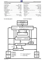
Page 2: ...3 1 Exploded View CD Drive 3 2 Spare Parts List 3 3 D Inhaltsverzeichnis Seite Allgemeiner Teil 1 2 1 7 Me ger te Hilfsmittel 1 2 Technische Daten 1 3 Servicetestprogramm 1 3 Ausbauhinweise 1 4 Bedien...

Page 3: ...0W Cabinet Material finish metal and polystyrene W x H x D 435 x 74 x 263mm Weight approx 3 5kg PLAY STOP T S S oder T dr cken Kopfschlitten f hrt nach aussen S oder T loslassen Kopfschlitten f hrt na...

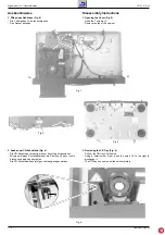
Page 4: ...Fig 1 P 2 Removing the CD Tray Fig 4 Pull out the CD tray until its stop Using a small screw driver push the catch B to the right to disengage it The CD tray can now be pulled out completely 2 Ausbau...

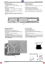
Page 5: ...er clip on the flexprint When pulling out the flexprint push the paper clip over the contacts MOS components ffnen eines Flexprint Steckers Opening a Flexprint Connector Kurzschliesen einer Flexprint...

Page 6: ...ncanberemoved Fig 9 and 10 Take care of the guide rail S when fitting the sled S S S S Fig 8 Fig 7 Fig 9 Fig 10 7 Ausbau des Antriebsriemens Fig 11 und 12 CD Laufwerk ausbauen Pkt 5 Mit einem kleinen...

Page 7: ...lliger Reihenfolge Die Auswahl der Reihenfolge bernimmt ein Zufallsgenerator Alle Bedienfunktionen bleiben wie bei normaler Wiedergabe erhalten Mit den Tasten S T k nnen Sie den n chsten oder vorherge...

Page 8: ...d SHUFFLE function By pressing SHUFFLE you activate the shuffle function which mixes up the order of the CD tracks A random number generator selects the order of the tracks to be played All operating...

Page 9: ...iagrams and Layout of PCBs CD 21 CD 22 Schaltpl ne und Druckplattenabbildungen Circuit Diagrams and Layout of PCBs GRUNDIG Service GRUNDIG Service Schaltpl ne und Druckplattenabbildungen Circuit Diagr...

Page 10: ...ttenabbildungen Circuit Diagrams and Layout of PCBs CD 21 CD 22 Schaltpl ne und Druckplattenabbildungen Circuit Diagrams and Layout of PCBs CD 21 CD 22 GRUNDIG Service GRUNDIG Service Verdrahtungsplan...

Page 11: ...5 3560 F 4 3562 F 5 3563 G 5 3564 F 1 3565 F 3 6535 D 5 6536 D 6 6537 E 6 6538 E 5 6540 C 2 6541 D 3 6542 B 4 6543 A 2 6544 C 4 6560 E 3 6561 E 4 6562 F 4 7535 D 7 7540 C 3 7541 A 5 7542 A 5 7543 B 7...

Page 12: ...2047 22uF 40V 2052 47nF 2014 330p 2050 220p 2002 220p 2005 22nF 2010 100nF 2071 22nF 2012 220p 2003 220p 2004 220p 2001 220p 2000 560p 2007 1n5 2006 2n7 2068 180p 2069 100n 2067 100n 2072 180p 2076 3...

Page 13: ...2103 100pF 2105 22pF 2109 22n 2102 1n 2114 47p 2112 47p 2113 100n 2600 22nF 2602 22n 2601 47n 2140 100n 2141 100n 2111 2n2 2100 47pF 2142 3R3 3115 22R 3145 3R3 3113 22R 3603 22uF 40V 2116 2110 22uF 4...

Page 14: ...S CURRENT SOURCES 2k2 3361 2k2 3362 3k9 3305 22k 3307 1k 3363 22k 3306 1k 3360 3k9 3304 18k 3300 15k 3301 47k 3370 220k 3368 47k 3371 220k 3369 2k2 3367 1k 3366 2k2 3365 1k 3364 47uF 25V 2303 47uF 25V...

Page 15: ...7 1403 D 3 1506 D 5 1507 D 6 1508 D 6 1510 D 7 1511 D 7 1530 D 7 2000 B 1 2001 B 1 2002 B 1 2003 B 1 2004 C 1 2005 B 1 2006 B 2 2007 B 1 2008 C 2 2009 C 2 2010 C 1 2011 C 2 2012 C 1 2013 C 1 2014 C 1...

Page 16: ...3 D 3 1506 D 5 1507 D 6 1508 D 6 1510 D 7 1511 D 7 1530 D 7 2000 B 1 2001 B 1 2002 B 1 2003 B 1 2004 C 1 2005 B 1 2006 B 2 2007 B 1 2008 C 2 2009 C 2 2010 C 1 2011 C 2 2012 C 1 2013 C 1 2014 C 1 2025...

Page 17: ...6 27 28 29 17 18 19 20 22 23 24 25 1 2 3 4 5 6 7 8 9 10 11 12 13 14 15 35 36 37 38 39 40 41 33 30 42 16 21 31 32 HOLD RESET XOUT XIN TEST VSS I O PORT R70 R71 R72 VDD VKK I O PORT OUTPUT RAM PORT TIMI...

Page 18: ...iste und Explosionszeichnungen Spare Parts List and Exploded Views CD 21 CD 22 GRUNDIG Service GRUNDIG Service 3 1 3 2 Ersatzteilliste und Explosionszeichnungen Spare Parts List and Exploded Views Exp...

Page 19: ...ty instructions shall be valid as provided by the Safety Service Manual part number 72010 800 00 as well as the respective national deviations C 2536 75954 069 22 ELKO 3300UF 20 16V D 6360 8309 215 14...

Page 20: ...b H Breitenfurter Stra e 43 45 Wien 00 43 1 8 11 17 0 GRUNDIG NEDERLAND B V Gebouw Amstelveste Joan Muyskenweg 22 CJ Amsterdam 00 31 20 5 68 15 68 GRUNDIG ITALIANA S P A Via G B Trener 8 Trento 00 39...

Reviews: