CD 21 / CD 22
Allgemeiner Teil / General Section
GRUNDIG Service
1 - 5
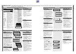
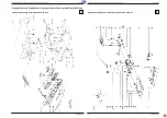
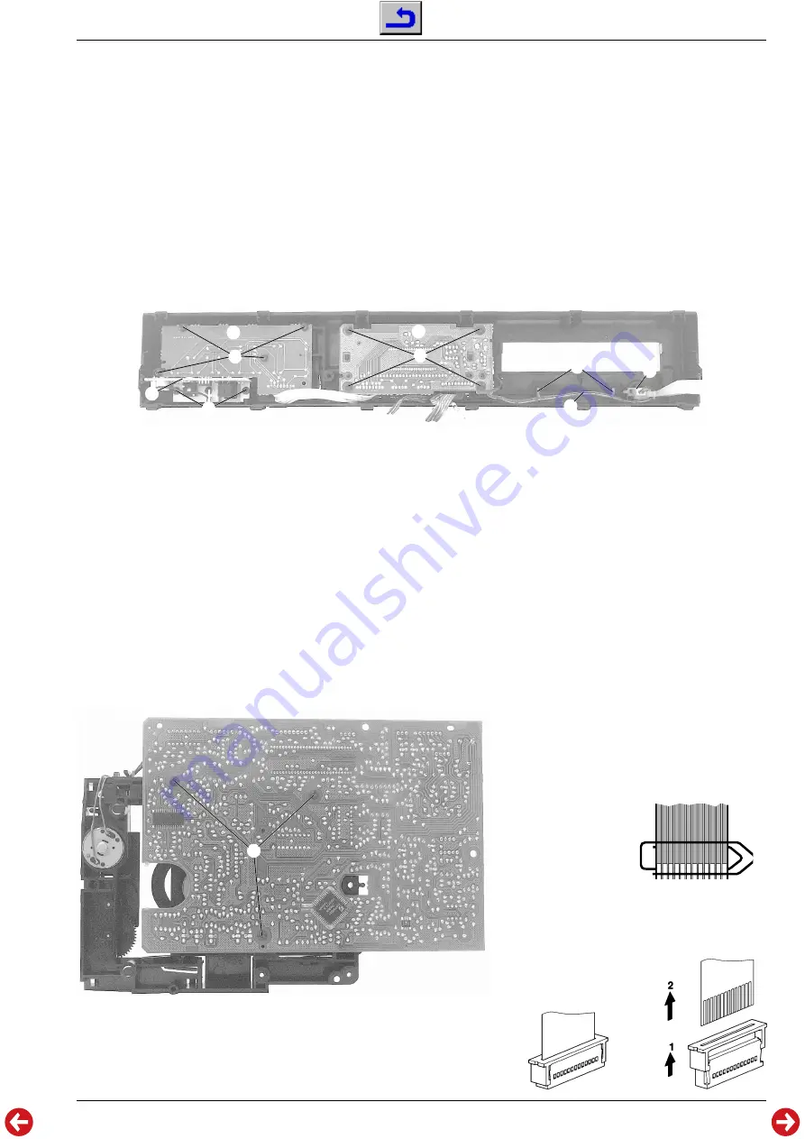
Fig. 5
F
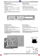
5. Ausbau des CD-Laufwerks
- CD Schublade ausbauen (Pkt. 2).
- Steckverbinder abziehen.
- Die 3 Schrauben
P
herausschrauben (Fig. 1).
- Das CD-Laufwerk mit der Chassisplatte herausnehmen.
- Beim Einbau darauf achten, daß das Laufwerk in den Führungen
Q
einrastet (Fig. 3).
- Die 3 Schrauben
R
herausschrauben (Fig. 6).
- Die Leiterplatte vorsichtig vom Laufwerk abheben und den
Flexprint-Stecker abziehen.
- Vor dem Öffnen des Flexprint-Steckers eine Büroklammer über
die Flexprint-Leitung schieben. Beim Herausziehen der
Flexprint-Leitung diese dann nach unten über die Kontakte
schieben (MOS-Bauteile)!
5. Removing the CD-Drive
- Remove CD tray (para 2).
- Disconnect the plug-in-connections.
- Unscrew the 3 screws
P
(Fig. 1).
- Remove the CD drive together with the chassis board.
- When mounting take care that the drive fints into the guides
Q
(Fig. 3).
- Unscrew the 3 screws
R
(Fig. 6).
- Carefully lift off the PCB from the drive and disconnect the flexprint
connector.
- Before opening the flexprint connector, put a paper clip on the
flexprint. When pulling out the flexprint, push the paper clip
over the contacts (MOS components)!
Öffnen eines Flexprint-Steckers
Opening a Flexprint Connector
Kurzschliesen einer Flexprint
Leitung
Shortening of a Flexprint
Fig. 6
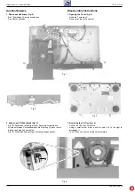
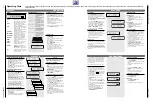
3. Ausbau der Frontblende
- CD Schublade ausbauen (Pkt. 2).
- Die 2 Schrauben
C
(Fig. 3) herausschrauben.
- Die 2 Rastnasen
D
(Fig. 1) und die 2 Rastnasen
E
(Fig. 3)
ausrasten.
4. Zerlegen der Frontblende (Fig. 5)
- Die 4 Schrauben
F
herausschrauben und die Leiterplatte
G
herausnehmen.
- Die 4 Schrauben
H
herausschrauben und die Leiterplatte
J
herausnehmen.
- Die 3 Schrauben
K
herausschrauben und die Leiterplatte
L
herausnehmen (nur CD 22).
- Beim Zusammenbau darauf achten, daß das Kabel
M
richtig in den
Führungen
N
liegt, da sonst die Netztaste
O
blockiert werden
kann.
3. Removing the Front Panel
- Remove CD tray (para 2).
- Undo the 2 screws
C
(Fig. 3).
- Disengage the 2 catches
D
(Fig. 1) and the 2 catches
E
(Fig. 3).
4. Disassembling of the Front Panel (Fig. 5)
- Undo the 4 screws
F
and remove the PCB
G
.
- Undo the 4 screws
H
and remove the PCB
J
.
- Undo the 3 screws
K
and remove the PCB
L
(only CD 22).
- When reassembling take care that the cable
M
fits into the
guides
N
as otherwise the mains button
O
might be blocked.
G
H
J
K
L
M
N
O
R


