background image

CD 21 / CD 22

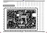
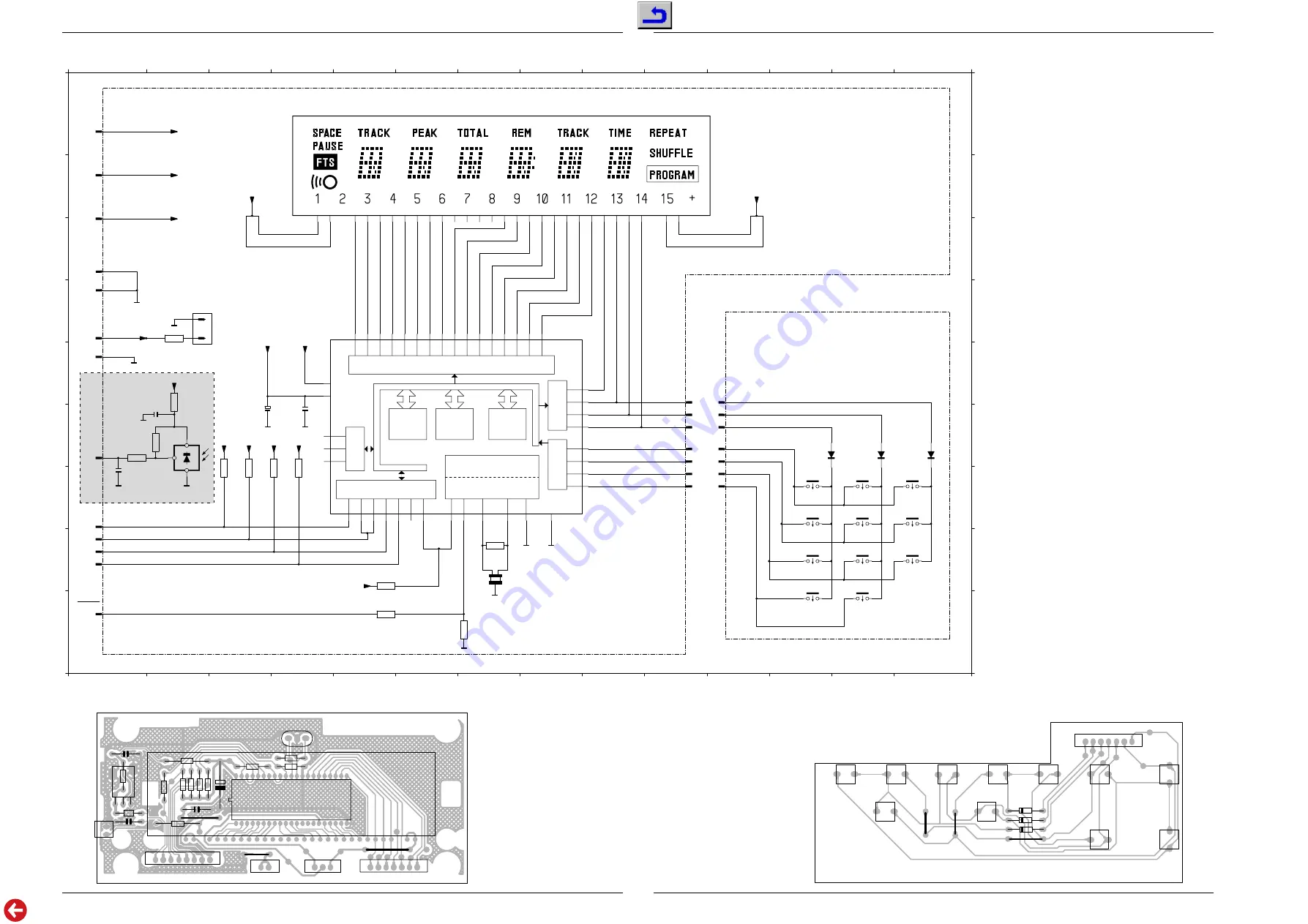
Schaltpläne und Druckplattenabbildungen / Circuit Diagrams and Layout of PCBs

CD 21 / CD 22

Schaltpläne und Druckplattenabbildungen / Circuit Diagrams and Layout of PCBs

GRUNDIG Service

GRUNDIG Service

2 - 17

2 - 18

-

VFTD

-

-

-

DISRES

SDIS

ACK

SDAT0

___
SCK

RC5

-

-

-

-

-

-

-

-

-

-

-

-

-

-

-

-

-

-

-

-

-

-VKK

+VKK

-

+5

GND


-

TO
LED

4

5

6

1

7

8

9

10

11

12

13

14

2

3

F

E

D

I

C

B

A

H

G

F

E

D

I

C

B

A

H

G

4

5

6

1

7

8

9

10

11

12

13

14

2

3

1k

3413

100R

3412

10k

3400

22k

3409

22k

3404

22k

3403

22k

3402

22k

3401

3k3

3408

220k

3411

22k

3410

270R

3414

1002

4

1002

3

1002

2

1002

1

1002

5

1002

6

1002

7

1003

7

1003

6

1003

5

1003

4

1003

3

1003

2

1003

1

1004

3

1004

1

1004

2

1001

1

1001 7

1001 8

1001 3

1001 4

1001 5

1001 6

1001 2

1007

1

1007 2

2

1008

1

2403

2n2

2402

47n

2401

22n

GP1U58XP

1

2

1040

IR

+5

+5

+5

+5

+VKK

-VKK

+VKK

-VKK

VFTD

+5

+5

VFTD

+5

+5

1450

8-BT-153GK

4

5

6

7

8

9

10

11

29

1

30

2

25

26

27

16

17

18

19

20

21

22

23

24

8G NC NC NC NC P1 P2 P3 P4 P5 P6 P7 P8 P9 P10 P11 P12

F+ F+'

F-

F-'

1G 2G 3G 4G 5G 6G 7G

1020

SHUFFLE

1023

REPEAT

1026

PLAY/REPLAY

1029

PAUSE

1030

PREVIOUS

1027

OPEN/CLOSE

1024

STOP/CP

1021

TIME

1022

PEAKSEARCH

FADER

1025

NEXT

1028

PROGRAM

1502
4MHz

22u/40V

2400

BAW62

6400

BAW62

6401

BAW62

6402

7400

TMP47C212

34

26

27

28

29

17

18

19

20

22

23

24

25

1

2

3

4

5

6

7

8

9

10

11

12

13

14

15

35

36

37

38

39

40

41

33

30

42

16

21

31

32

HOLD

RESET

XOUT

XIN

TEST

VSS

I/O

PORT

R70

R71

R72

VDD

VKK

I/O PORT

OUTPUT

RAM

PORT

TIMING CONTROLLER

CLOCK

ROM

INPUT

PORT

PORT

OUT

K02

K01

K00

P23

P22

P21

P20

K03

R91

P40

R92

P42

R90

P41

R81

P51

R80

P52

P53

R83

P43

____

P60

_____

P61

P62

P63

P10

P11

R82

P12

P13

P50

CPU

ONLY CD 22

-20V

-17V

-22V

10

40

1001

2402

2403

3412

3400

3408

9310

3414

2401

3413

1008

340

3

3402

1450

3401

340

4

1007

1004

2400

7400

9311

3409

3410

3411

1502

1003

9301

1

30

1

1

1

1

1

1020

1026

1029

6400

9303

9302

930

4

1024

1028

6401

1022

1023

6402

1025

1021

1027

1002

1030

1

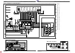
Bedien- und Display-Teil / Control and Display Part

Display-Platte / Display Board

Bedien-Platte / Control Board

Bauteil

X

Y

Component

1001

E

1

1001

G

1

1001

I

1

1001

H

1

1001

H

1

1001

H

1

1001

G

1

1001

E

1

1002

E 11

1002

F 11

1002

F 11

1002

F 11

1002

F 11

1002

G 11

1002

G 11

1003

E 10

1003

F 10

1003

F 10

1003

F 10

1003

F 10

1003

G 10

1003

G 10

1004

B

1

1004

A

1

1004

B

1

1007

D

1

1007

C

1

1008

E

2

1020

G 12

1021

G 13

1022

G 14

1023

G 12

1024

G 13

1025

G 14

1026

H 12

1027

H 13

1028

H 14

1029

H 12

1030

H 13

1040

G

2

1450

A 10

1502

H

7

2400

F

4

2401

F

4

2402

F

2

2403

G

1

3400

F

2

3401

G

3

3402

G

3

3403

G

4

3404

G

4

3408

I

5

3409

H

5

3410

I

7

3411

H

7

3412

F

2

3413

G

1

3414

E

2

6400

F 12

6401

F 13

6402

F 14

7400

D

8

Summary of Contents for CD 21

Page 1: ...Nr Part No 72010 800 00 Grundig Service Hotline Deutschland TV SAT VCR LiveCam HiFi Audio Car Audio Telekommunikation Fax 0180 52318 41 0180 52318 42 0180 52318 43 0180 52318 44 0180 52318 45 0180 52...

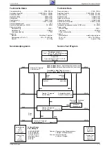
Page 2: ...3 1 Exploded View CD Drive 3 2 Spare Parts List 3 3 D Inhaltsverzeichnis Seite Allgemeiner Teil 1 2 1 7 Me ger te Hilfsmittel 1 2 Technische Daten 1 3 Servicetestprogramm 1 3 Ausbauhinweise 1 4 Bedien...

Page 3: ...0W Cabinet Material finish metal and polystyrene W x H x D 435 x 74 x 263mm Weight approx 3 5kg PLAY STOP T S S oder T dr cken Kopfschlitten f hrt nach aussen S oder T loslassen Kopfschlitten f hrt na...

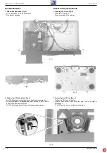
Page 4: ...Fig 1 P 2 Removing the CD Tray Fig 4 Pull out the CD tray until its stop Using a small screw driver push the catch B to the right to disengage it The CD tray can now be pulled out completely 2 Ausbau...

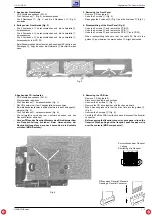
Page 5: ...er clip on the flexprint When pulling out the flexprint push the paper clip over the contacts MOS components ffnen eines Flexprint Steckers Opening a Flexprint Connector Kurzschliesen einer Flexprint...

Page 6: ...ncanberemoved Fig 9 and 10 Take care of the guide rail S when fitting the sled S S S S Fig 8 Fig 7 Fig 9 Fig 10 7 Ausbau des Antriebsriemens Fig 11 und 12 CD Laufwerk ausbauen Pkt 5 Mit einem kleinen...

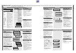
Page 7: ...lliger Reihenfolge Die Auswahl der Reihenfolge bernimmt ein Zufallsgenerator Alle Bedienfunktionen bleiben wie bei normaler Wiedergabe erhalten Mit den Tasten S T k nnen Sie den n chsten oder vorherge...

Page 8: ...d SHUFFLE function By pressing SHUFFLE you activate the shuffle function which mixes up the order of the CD tracks A random number generator selects the order of the tracks to be played All operating...

Page 9: ...iagrams and Layout of PCBs CD 21 CD 22 Schaltpl ne und Druckplattenabbildungen Circuit Diagrams and Layout of PCBs GRUNDIG Service GRUNDIG Service Schaltpl ne und Druckplattenabbildungen Circuit Diagr...

Page 10: ...ttenabbildungen Circuit Diagrams and Layout of PCBs CD 21 CD 22 Schaltpl ne und Druckplattenabbildungen Circuit Diagrams and Layout of PCBs CD 21 CD 22 GRUNDIG Service GRUNDIG Service Verdrahtungsplan...

Page 11: ...5 3560 F 4 3562 F 5 3563 G 5 3564 F 1 3565 F 3 6535 D 5 6536 D 6 6537 E 6 6538 E 5 6540 C 2 6541 D 3 6542 B 4 6543 A 2 6544 C 4 6560 E 3 6561 E 4 6562 F 4 7535 D 7 7540 C 3 7541 A 5 7542 A 5 7543 B 7...

Page 12: ...2047 22uF 40V 2052 47nF 2014 330p 2050 220p 2002 220p 2005 22nF 2010 100nF 2071 22nF 2012 220p 2003 220p 2004 220p 2001 220p 2000 560p 2007 1n5 2006 2n7 2068 180p 2069 100n 2067 100n 2072 180p 2076 3...

Page 13: ...2103 100pF 2105 22pF 2109 22n 2102 1n 2114 47p 2112 47p 2113 100n 2600 22nF 2602 22n 2601 47n 2140 100n 2141 100n 2111 2n2 2100 47pF 2142 3R3 3115 22R 3145 3R3 3113 22R 3603 22uF 40V 2116 2110 22uF 4...

Page 14: ...S CURRENT SOURCES 2k2 3361 2k2 3362 3k9 3305 22k 3307 1k 3363 22k 3306 1k 3360 3k9 3304 18k 3300 15k 3301 47k 3370 220k 3368 47k 3371 220k 3369 2k2 3367 1k 3366 2k2 3365 1k 3364 47uF 25V 2303 47uF 25V...

Page 15: ...7 1403 D 3 1506 D 5 1507 D 6 1508 D 6 1510 D 7 1511 D 7 1530 D 7 2000 B 1 2001 B 1 2002 B 1 2003 B 1 2004 C 1 2005 B 1 2006 B 2 2007 B 1 2008 C 2 2009 C 2 2010 C 1 2011 C 2 2012 C 1 2013 C 1 2014 C 1...

Page 16: ...3 D 3 1506 D 5 1507 D 6 1508 D 6 1510 D 7 1511 D 7 1530 D 7 2000 B 1 2001 B 1 2002 B 1 2003 B 1 2004 C 1 2005 B 1 2006 B 2 2007 B 1 2008 C 2 2009 C 2 2010 C 1 2011 C 2 2012 C 1 2013 C 1 2014 C 1 2025...

Page 17: ...6 27 28 29 17 18 19 20 22 23 24 25 1 2 3 4 5 6 7 8 9 10 11 12 13 14 15 35 36 37 38 39 40 41 33 30 42 16 21 31 32 HOLD RESET XOUT XIN TEST VSS I O PORT R70 R71 R72 VDD VKK I O PORT OUTPUT RAM PORT TIMI...

Page 18: ...iste und Explosionszeichnungen Spare Parts List and Exploded Views CD 21 CD 22 GRUNDIG Service GRUNDIG Service 3 1 3 2 Ersatzteilliste und Explosionszeichnungen Spare Parts List and Exploded Views Exp...

Page 19: ...ty instructions shall be valid as provided by the Safety Service Manual part number 72010 800 00 as well as the respective national deviations C 2536 75954 069 22 ELKO 3300UF 20 16V D 6360 8309 215 14...

Page 20: ...b H Breitenfurter Stra e 43 45 Wien 00 43 1 8 11 17 0 GRUNDIG NEDERLAND B V Gebouw Amstelveste Joan Muyskenweg 22 CJ Amsterdam 00 31 20 5 68 15 68 GRUNDIG ITALIANA S P A Via G B Trener 8 Trento 00 39...

Reviews: