background image

1 - 6

GRUNDIG Service

Allgemeiner Teil / General Section

CDP-S 150

Ausbauhinweise

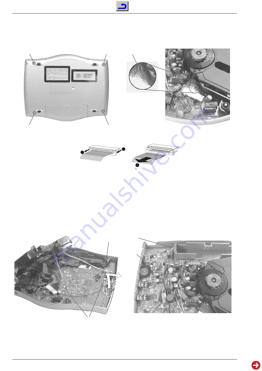
1. Gehäuseoberteil abnehmen
- 4 Schrauben 

A

 herausdrehen (Fig. 1).

- Gehäuseoberteil (mit CD-Fachdeckel) abnehmen.

Disassembly Instructions

1. Removing the Top of the Cabinet
- Undo 4 screws 

A

 (Fig. 1).

- Remove the top of the cabinet (with the CD compartment lid).

Fig. 5

Fig. 4

Fig. 2

Fig. 3

Fig. 1

2. CD-Laufwerk ausbauen
Achtung: Die Lasereinheit ist sehr empfindlich gegen statische
Aufladungen (MOS-Bauteile)!
Deshalb muß vor Abziehen der Steckverbindung eine Schutzlötstelle

B

 (Fig. 2) auf der Flexprintleitung angebracht werden, um eine

Zerstörung der Laserdiode durch statische Aufladung zu vermeiden.
- Gehäuseoberteil abnehmen (siehe Pkt. 1).
- Flexprinthalter öffnen (Fig. 3).
- Flexprintleitung aus Flexprinthalter ziehen.
- Laufwerkzuleitungen von der Hauptplatte ablöten (S+/rot, S-/

schwarz, T-/orange, T+/blau, 2 x RST/weiß).

- Laufwerk herausnehmen.

2. Removing the CD Drive Mechanism
Attention: The laser unit is very sensitive to static charges (MOS
components)!
Therefore the flexprint must be provided with a protective soldered joint

B

 (Fig. 2) before unplugging the connector to avoid damage to the

laser diode by static charges.
- Remove the top of the cabinet (see para 1).
- Open the flexprint holder (Fig. 3).
- Pull the flexprint out of its flexprint holder.
- Unsolder the drive mechanism connecting leads on the main

board (S+/red, S-/black, T-/orange, T+/blue, 2 x RST/white).

- Take out the drive mechanism.

2

1

1

3. Hauptplatte ausbauen
- CD-Laufwerk ausbauen (siehe Pkt. 2).
- 2 Schrauben 

C

 (Fig. 4) und Schraube 

D

 (Fig. 5) herausdrehen.

- Batteriekontakte 

E

 (Fig. 4) und 

F

 (Fig. 5) aus dem Gehäuseunter-

teil herausziehen.

- Hauptplatte in Pfeilrichtung A (Fig. 4) anheben und herausnehmen.

A

A

A

A

A

B

C

D

F

E

3. Removing the Main Board
- Remove the CD drive mechanism (see para 2).
- Undo 2 screws 

C

 (Fig. 4) and screw 

D

 (Fig. 5).

- Pull out the battery contacts 

E

 (Fig. 4) and 

F

 (Fig. 5).

- Lift the main board in the direction of the arrow A (Fig. 4) and take

it out.

Summary of Contents for CDP-S 150

Page 1: ...ice Service Manual Service Manual Btx 32700 Sachnummer Part Number 72010 752 70 nderungen vorbehalten Subject to alteration Printed in Germany VK231 0797 CDP S 150 Sach Nr Part No 72010 752 70 Sicherh...

Page 2: ...d Spare Parts List 3 1 3 2 Exploded Views 3 1 Spare Parts List 3 2 j Inhaltsverzeichnis Seite Allgemeiner Teil 1 2 1 7 Me ger te Me mittel 1 2 Technische Daten 1 3 Servicehinweise 1 3 Bedienhinweise 1...

Page 3: ...metal cap on the negative pole is stripped more than 3mm as illustrated Otherwise the accumulator will not be charged Laser Unit When removing the drive mechanism the flexprint must be provided with...

Page 4: ...s Plattentellers sitzt Neben den herk mmlichen 12 cm CD s k nnen auch 8 cm CD s ohne Adapter verwendet werden Schlie en Sie den Deckel durch leichtes Dr cken auf dessen rechte Seite Der CD Spieler tas...

Page 5: ...ew ones 3 mm min POWER SUPPLY Open the lid by pressing both PUSH OPEN buttons and lifting the lid gently Insert an audio CD printed side up Push gently on the CD center so that it fits onto the hub In...

Page 6: ...Laufwerk herausnehmen 2 Removing the CD Drive Mechanism Attention The laser unit is very sensitive to static charges MOS components Thereforetheflexprintmustbeprovidedwithaprotectivesolderedjoint B Fi...

Page 7: ...g 8 mit einem Schraubendreher in Pfeilrichtung B dr cken und von au en mit einer Zange herauszie hen I H I I H J G G Fig 9 Servicestellung Service position Fig 7 K Fig 8 4 Removing the Keyboard Panel...

Page 8: ...lattenabbildung Circuit Diagrams and Layout of PCB CDP S 150 2 1 GRUNDIG Service Schaltpl ne und Druckplattenabbildung Circuit Diagrams and Layout of PCB Druckplattenabbildung Layout of PCB Best ckung...

Page 9: ...7 2 1 1 7 2 1 1 5 2 3 1 6 2 1 0 2 0 0 0 0 PIN 19 20 21 22 23 24 25 26 27 28 29 30 31 32 33 34 35 36 V 1 7 1 7 1 6 2 5 1 7 1 7 1 8 1 7 1 7 1 7 0 1 7 1 7 1 7 Schaltbild Circuit Diagram BEI DEN ANGEGEBE...

Page 10: ...7 6 POWER SWITCH IN 1 PRE GND IN 2 REF MUTE SWITCH OUT 1 POWER GND OUT 2 VCC LA 4534 IC1 BA4510F IC2 LA4534M LCD CONTROL DRIVER WATCH DOG TIMER CLOCK GEN HALT STOP ROM 8192 x 8 PC 12 I R S P Y 4 X 4 I...

Page 11: ...atzteilliste und Explosionszeichnungen Spare Parts List and Exploded Views GRUNDIG Service 3 1 2 Ersatzteilliste und Explosionszeichnungen Spare Parts List and Exploded Views Explosionszeichnungen Exp...

Page 12: ...S FIN D GB F I P E NL DK S FIN 72010 752 70 SERVICE MANUAL D GB SERVICE MANUAL D GB ERSETZT AUSGABE 4 97 SUBSTITUTE EDITION 4 97 POS NR SACHNUMMER BEZEICHNUNG POS NO PART NUMBER DESCRIPTION POS NR SA...

Reviews: