ENGLISH
68
GENERAL OPERATING PRINCIPLE OF THE TV
-----------
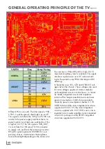
Different PSUs are used. The 2nd signal is "VBL_
CTRL"; it switches panel's back-lights on or off.
This signal is sent from the 14th pin of S100 con-
nector to the power supply and from there, to
panel inverter; rear lights are switched on if this
is higher (3.3 V). The 3rd signal is "BRI_ADJ";
it is sent from the 13th pin of S100 connector
to supply unit, and from there to panel inverter.
BRI_ADJ signal represents DIMMING in our
previous chassis; it determines the brightness
level of backlight depending on the value set in
the user menu. When BRI_ADJ is high (3.3 V)
maximum brightness level is reached. This signal
can be a square wave or a DC value accord-
ing to the panels using PWM dimming and DC
dimming.
In Stand-By, only VCC_STB and STBC3V3 volt-
ages act on the chassis. These voltages are used
for core voltage supplies of various modules
and integrated circuits in GM chassis. In Stand-
By mode, integrated circuits and regulators
remain off as long as possible to ensure lower
power consumption. In GM-chassis products,
Stand-By power consumption is below 0.5 W.
DDR3 RAM and the main integrated circuit are
supplied with VCC1V5; the main integrated
circuit is supplied with VCC1V18; tuners, Lnb in-
tegrated circuit, audio amplifier, main integrated
circuit, I2C pull-ups and the RESET integrated
circuit are supplied with VCC3V3.
Summary of Contents for COREMAX M1 PROJECT GM
Page 1: ...COREMAX M1 PROJECT GM CHASSIS SERVICE MANUAL...
Page 66: ...ENGLISH 66 GENERAL OPERATING PRINCIPLE OF THE TV Block Diagram...
Page 81: ...ENGLISH 81 CHASSIS DIAGRAMMATIC IMAGES Chassis DC Socket DC voltages...
Page 82: ...ENGLISH 82 CHASSIS DIAGRAMMATIC IMAGES...
Page 83: ...ENGLISH 83 CHASSIS DIAGRAMMATIC IMAGES Terrestrial tuner Satellite tuner...
Page 84: ...ENGLISH 84 CHASSIS DIAGRAMMATIC IMAGES USB...
Page 86: ...ENGLISH 86 FAILURE ERROR ANALYSES...
Page 88: ...ENGLISH 88 FAILURE ERROR ANALYSES...


