69
ENGLISH
OPERATING PRINCIPLES OF THE CIRCUIT COPNENTS
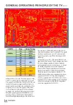
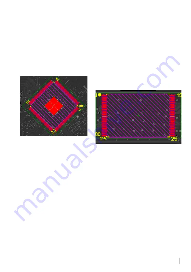
IC200 Main integrated circuit
(IC-
SMD MSD92LBSW2 BGA)
Main integrated circuit IC200's specifications
are: FHD support, digital (DVB-T/T2/C/S2) and
analog broadcast demodulator, USB recording
feature, broadcast and A/V decoder (NTSC/
PAL/SECAM) Full HD 50 Hz support, MPEG-2
and MPEG-4 support, 32-Bit Linux based pro-
cessor, Audio and sub-woofer processor and
interface, 3 USB 2.0, 3 HDMI, DDR3 RAM,
HEVC H.265 support.
The main integrated circuit collects and process-
es data coming from all inputs and sends audio
and video output to the speaker over amplifier
and to the panel over LVDS line. This integrated
circuit has more than 500 legs. Special equip-
ment is required for installation and removal.
Therefore, these integrated circuits are designed
with very low error ratios. If you suspect any er-
ror with main IC on TV, firstly supplies of this IC
should be checked. There are 4 input supplies
as 1.5 V, 1.1 8V, 1.8 V and 3.3 V. Extremely
low or high ratings of these supplies might cause
image freezing, some sources' not functioning
or losing the picture completely. Besides, the
problem might be originated in software, flash,
crystal or RAM. If there is a problem, we cannot
be sure that it is originated in IC before check-
ing it out.
While turning the TV on, main IC switches on
the system by reading the flash and turns on the
power supply by switching the "POWER_SW"
signal to high. Then, panel signals "BRI_ADJ"
(Sets back-light brightness) and “VBL_CTRL”
(turns on back-light) turn on panel back-light and
the image appears on TV.
There is no separate RAM on the chassis.
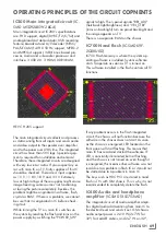
IC700 Nand flash
(IC-SMD K9F-
2G08U0D)
IC700 Flash memory is where the system op-
erating software is installed. System software
starts to operate as soon as TV is turned on.
This software installed in the flash controls all TV
functions.
If any problem occurs in the flash integrated
circuit, the chassis will not function because the
software in the chassis does not start. As soon
as the chassis is energized, LED located on the
front panel will start flashing. This means that
main IC has read and started the software. IF
LED is constantly illuminated but not flashing,
and the chassis is not turned on even though it
is energized, this means either software was not
read due to a problem in flash IC or it could not
be started due to a problem in main IC.
The keys such as HDCP, CI are stored in nand
flash in TVs with GM chassis. This is why it is not
recommended to completely delete the flash.
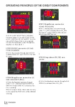
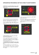
IC400 Audio and headphone
amplifier
(IC-SMD TAS5753MD)
The integrated circuit of audio amplifier ampli-
fies digital audio data coming from main IC to
the desired level and sends it out. GM chassis
audio output power is 2x10 W (2x7 W for
32") for LedART cabins, and 2x7 W on 32",
Summary of Contents for COREMAX M1 PROJECT GM
Page 1: ...COREMAX M1 PROJECT GM CHASSIS SERVICE MANUAL...
Page 66: ...ENGLISH 66 GENERAL OPERATING PRINCIPLE OF THE TV Block Diagram...
Page 81: ...ENGLISH 81 CHASSIS DIAGRAMMATIC IMAGES Chassis DC Socket DC voltages...
Page 82: ...ENGLISH 82 CHASSIS DIAGRAMMATIC IMAGES...
Page 83: ...ENGLISH 83 CHASSIS DIAGRAMMATIC IMAGES Terrestrial tuner Satellite tuner...
Page 84: ...ENGLISH 84 CHASSIS DIAGRAMMATIC IMAGES USB...
Page 86: ...ENGLISH 86 FAILURE ERROR ANALYSES...
Page 88: ...ENGLISH 88 FAILURE ERROR ANALYSES...

