ENGLISH
70
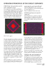
OPERATING PRINCIPLES OF THE CIRCUIT COMPONENTS
2x10 W on 40" and 43" for Crystal cabins.
For LUNA cabins, it is 2x3 W on 24", 2x6 W
on 32", 2x8 W on 40", 43" and 50". As is the
case with KP chassis, there is not a separate
circuit for the headphone socket. Headphone
amplifier is in the audio IC. I
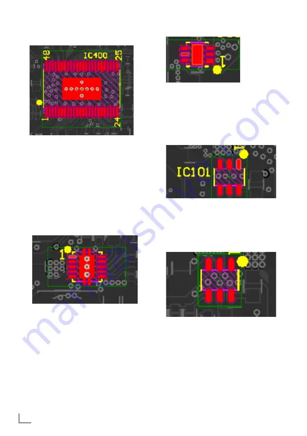
IC103 DC-DC converter
(IC-SMD
TPS54335ADRCR)
IC103 is the converter through which VCC5V
is obtained from VCC input. VCC5V is the main
IC supply.
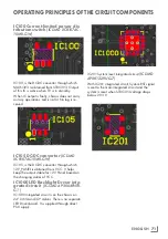
IC104 Step-Down converter
(IC-
SMD XC6222D151ER-G)
IC104 is the Step-down converter through
which +1.5 V is obtained from MAIN3V3 or
STBC3V3. Output of this IC is not active when
TV is in stand-by.
When IC output is faulty, chassis does not carry
out any operations. RAM error will be obtained
in the log.
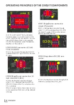
IC101 Step-Down converter
IC-SMD TPS562200)
I
C101, is the Step-down converter through
which +1.1_CPU is obtained from VCC_STB.
The Main IC supply of FRC and the relevant
board is provided from here.
I
IC102 Step-down DC/DC con-
verter
IC102 is the Step-down converter through which
STBC3V3 is obtained from VCC_STB.
Summary of Contents for COREMAX M1 PROJECT GM
Page 1: ...COREMAX M1 PROJECT GM CHASSIS SERVICE MANUAL...
Page 66: ...ENGLISH 66 GENERAL OPERATING PRINCIPLE OF THE TV Block Diagram...
Page 81: ...ENGLISH 81 CHASSIS DIAGRAMMATIC IMAGES Chassis DC Socket DC voltages...
Page 82: ...ENGLISH 82 CHASSIS DIAGRAMMATIC IMAGES...
Page 83: ...ENGLISH 83 CHASSIS DIAGRAMMATIC IMAGES Terrestrial tuner Satellite tuner...
Page 84: ...ENGLISH 84 CHASSIS DIAGRAMMATIC IMAGES USB...
Page 86: ...ENGLISH 86 FAILURE ERROR ANALYSES...
Page 88: ...ENGLISH 88 FAILURE ERROR ANALYSES...


