background image

Châssis / Chassis 12.6

GRUNDIG Service

Partie générale / General Section

1 - 12

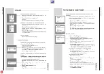
2. Remplacement du puce mémoire IC402
Après le remplacement du IC402 il faut effectuer tous les réglages
dans le mode de service suivant le tableau "Réglages de base" 
(point 1).

3. Mode hôtel

3.1 Activer le mode hôtel
Le mode hôtel est activé dans le mode de service (menu 1).

Sélectionner le point de menu "Hôtel" par la touche 

Ƕ

 ou 

ǵ

, puis

sélectionner "Oui" avec la touche 

Ǹ

 ou 

Ƿ

. Quitter ensuite le mode

de service.
Lorsque le mode hôtel est activé:
- dans le "Dialog Center" seulement le "Arrêt prog." ne peut plus

être sélectionné.

- le volume sonore sélectionné en dernier est le volume maximal

qui est mémorisé (H.VOL dans le menu 1 dans le mode de ser-
vice).

3.2 Désactiver le mode hôtel
Maintenir enfoncée la touche "

ǺǺǺǺ

" de la téléecommande tout en met-

tant l‘appareil en service par la touche secteur. Activer le menu 1
par la touche "rouge". Sélectionner le point de menu "Hôtel" dans le
menu 1 dans le mode de service par la touche 

Ƕ

 ou 

ǵ

puis sélec-

tionner "Non" par la touche 

Ǹ

 ou 

Ƿ

.

4. Désactiver en permanence la clé parentale
Entrer le numéro "7038" pour désactiver la clé parentale en perma-
nence.

5. ATS-Reset (Automatic Tuning System)
Amener la touche secteur en position "MARCHE" tout en appuyant
sur la touche de la télécommande 

Ƿ

 –> Sélection de la langue –>

Sélection du pays –> "OK".
Le système de recherche automatique de programmes s‘arrête sur
chaque émetteur digne d‘être reçu (AFC et coïncidence) et mémori-
se automatiquement les donnés d‘émisson avec le standard corre-
spondant. Ensuite la recherche continue.
Appuyer sur la touche "TXT" pour quitter la recherche ATS. Si la
fonction ATS est quittée avant qu‘un  émetteur soit trouve, la fonc-
tion ATS est relancée automatiquement après la mise en service de
l‘appareil.

6. Numéro de version du logiciel
Le numéro de version du logiciel est affiché après avoir quitté le
mode de service.

7. Réglages d'usine
Apppeler les régalges d'usine par la touche "

Ǻ

" (Dialog Center)  –>

Service –> "OK" –> Réglages d'usine, puis mémoriser par "OK".

8. Numéro de programme maximal (point d'inversion):
Lorsque la fonction ATS est terminée, le point d'inversion est ajouté
automatiquement à la fin du tableau d'émetteurs (affichage 0000) et
peut  être déplacé dans le tableau comme toute autre position de
programme.

2. Change of the Memory IC402
After changing IC402 all settings in the service mode must be done
according to the table "Basic Settings" (point 1).

3. Hotel Mode

3.1 Activating the Hotel Mode
The Hotel Mode can be activated via Service Mode (menu 1).
Select point of menu "Hotel" with button 

Ƕ

 or 

ǵ

, with button

Ǹ

 or 

Ƿ

set to "YES". End the Service Mode.

With activated Hotel Mode:
- only the "SLEEP TIMER" can be selected in the "Dialog Center".
- the last volume setting is stored as the maximum level possible

(H.VOL in menu 1 of the Service Mode).

3.2 Deactivating the Hotel Mode
Press and hold button "

ǺǺǺǺ

" on the remote control handset while swit-

ching the TV set on with the mains switch. Activate menu 1 via but-
tons "red". Select point of menu "Hotel" in menu 1 of Service Mode
via button 

Ƕ

 or 

ǵ

, set with button 

Ǹ

 or 

Ƿ

to "NO".

4. Cancelling the Parental Lock Continuously
To cancel the parental lock enter the number "7038".

5. ATS Reset (Automatic Tuning System)
Press the power "ON" button while pressing button 

Ƿ

 on the Remo-

te Control –> Language Selection –> Country Selection –> "OK".
The ATS system stops at every station of acceptable reception qua-
lity (AFC and coincidence) and stores the station data and the re-
spective standard automatically. The system then continues sear-
ching.
Pressing the "TXT" button stops the ATS function. If ATS will be
stopped before storing anyone station, ATS will start again when
switching on the TV again.

6. Software Version Number
The software version number is shown after ending the service
mode.

7. Presets
Press Button "

Ǻ

" to select "Preset" via the Dialog Center –> Service

–> "OK" –> "Factory settings", store with "OK".

8. Maximum Programme Number (Reversing Point):
The reversing point will be automatically added to the station table
(indication 0000) and can be sorted like each other channel station.

Summary of Contents for DAVIO 37 P 37-2201

Page 1: ...aire n cessaire pour la maintenance Additionally required Service Documents for the Complete Service Service Manual Service Training TV Service Manual Chassis 12 6 DAVIO 37 P 37 2201 FR GBA0502 DAVIO...

Page 2: ...Table of Contents Page General Section 1 3 1 12 General Notes 1 3 Safety Advice 1 3 Service Note 1 3 Tables of Norms and Channels 1 4 Technical Data 1 7 Operating Hints DAVIO 55 T55 4201 FR TOP only F...

Page 3: ...keyboard control panel picture tube panel deflection unit loudspeaker and so on On completion of the repairs the leads must be laid out as originally fitted at the factory to avoid later failures or d...

Page 4: ...50 C 51 703 25MHz 711 25MHz 52 53 54 55 C 52 C 53 719 25MHz 727 25MHz C 54 C 55 735 25MHz 743 25MHz 56 57 58 59 C 56 C 57 751 25MHz 759 25MHz C 58 C 59 767 25MHz 775 25MHz 60 61 62 63 C 60 C 61 783 2...

Page 5: ...Hz 380 75MHz Y S 62 392 75MHz Interbande Special Channels Norme L L Norm L L Ecart son image Sound vision spacing 6 5MHz Pas des canaux Channel bandwidth 10 5MHz Nom Name S 70 S 71 S 72 N canal Channe...

Page 6: ...dwidth 8MHz Nom Name S 21 S 22 S 23 N canal Channel no S 21 Fr quence image Vision carrier frequency 303 25MHz S 22 S 23 311 25MHz 319 25MHz S 24 S 25 S 26 S 27 S 24 S 25 327 25MHz 335 25MHz S 26 S 27...

Page 7: ...sung 90 50Hz 99 2 AV PLL fr quence synthesizer Tuning UHF VHF PLL frequency synthesizer tuning UHF VHF 99 2 AV B G L L PAL SECAM via AV NTSC 4 43MHz B G L L PAL SECAM via AV NTSC 4 43MHz Mono 5W ront...

Page 8: ...l Section 1 8 Mode d emploi Ce chapitre contient des extraits du mode d emploi Pour toutes informations suppl mentaires veuillez vous r f rer au mode d emploi sp cifique chaque appareil dont le num ro...

Page 9: ...GRUNDIG Service 1 9 Partie g n rale General Section Ch ssis Chassis 12 6...

Page 10: ...ALPS Version du tuner version of tuner PHILIPS P SONIC AGC TEMIC voir alignement see adjustment Version du tuner version of tuner Version du tuner version of tuner x Version du tuner version of tuner...

Page 11: ...nement see adjustment R DRV B DRV voir alignement see adjustment voir alignement see adjustment Menu 4 touche bleue button blue SCRN SECBL voir alignement see adjustment voir alignement see adjustment...

Page 12: ...usine par la touche Dialog Center Service OK R glages d usine puis m moriser par OK 8 Num ro de programme maximal point d inversion Lorsque la fonction ATS est termin e le point d inversion est ajout...

Page 13: ...teuse son d sactiv e via l antenne Canal 32 70 1dB V Activerlemodedeservice choisirlemenu1 touche rouge A l aide de ou s lectionner AGC A l aide de ou s lectionner 2 AGC Activer le mode de service cho...

Page 14: ...CUT A l aide de la touche ou s lectionner R CUT A l aide de la touche ou s lectionner B CUT A l aide de la touche ou s lectionner R DRV A l aide de la touche ou s lectionner B DRV Seulement n cessaire...

Page 15: ...nd Tuner Colour video generator Feed in a colour scale with switched off sound carrier via the aerial channel 32 70 1dB V Start the Service Mode call up the dialog line AGC via menu 1 red button with...

Page 16: ...with button or Only necessary if deadjusted Adjust according to the test pattern using button or Adjust according to the test pattern using button or Adjust according to the test pattern using button...

Page 17: ...lectriques Layout of PCBs and Circuit Diagrams GRUNDIG Service 3 1 TV marche on Standby TV marche on Standby m u i v x Oscillogrammes du ch ssis Oscillograms Chassis Board Circuit imprim s et sch mas...

Page 18: ...Circuit imprim s et sch mas lectriques Layout of PCBs and Circuit Diagrams Ch ssis Chassis 12 6 3 2 GRUNDIG Service y u v x y m i v x y m u i v...

Page 19: ...ut of PCBs and Circuit Diagrams GRUNDIG Service Ch ssis Chassis 12 6 Circuit imprim s et sch mas lectriques Layout of PCBs and Circuit Diagrams 3 3 3 4 C I Ch ssis Principal Chassis Board C te composa...

Page 20: ...it Diagrams Ch ssis Chassis 12 6 GRUNDIG Service Circuit imprim s et sch mas lectriques Layout of PCBs and Circuit Diagrams Ch ssis Chassis 12 6 3 5 3 6 C I Ch ssis Principal Chassis Board C te soudur...

Page 21: ...0p 500V C517 H LIN L502 HORIZONTAL X502 4 3 2 1 FBT TR501 8 4 1 11 9 7 6 2 5 10 3 G2 FOCUS EHT 6 8n 1 5kV C513 9V R521 47u 35V C512 2 2uH L501 27R 0 5W R518 4 7k R519 BU808DFI T504 82R 3W R517 10k R51...

Page 22: ...SW402 SW401 1k R413 VDD_2 5V 1N4148 D404 10n C409 9V 47n C412 10k R419 2 2k R420 3 3V 1k R423 10k R418 BC848 T403 220p C413 1k R466 10n C414 10k R427 10k R433 10n C417 BC848 T404 BC848 T405 MULTIMEDIA...

Page 23: ...6 VERT_OUT 45 SAW TOOTH 44 AUD_ DECOUPLING 43 AFC1 42 HORIZ_OUT 41 H_VCC 6 3V 40 3 58 39 HOR_SYNC 38 VID_IN_SYNC 37 C APC2 36 VIDEO_OUT 35 VCC 4 7V 34 EXT_VIDEO_OUT 33 VCC 32 EXT_AUDIO_OUT 31 BLK LEVE...

Page 24: ...R720 220R opt R719 CRT X701 5 4 3 2 1 SMPS AQUA G2 CRT X703 3 2 1 155V crt 100n 250V C708 2 2n C707 1 5K R714 1 5K R708 1 5K R704 9V_ 9V_ 2 7k R716 crt 100R R718 390p C706 crt 470R R717 155V 15k 1W R7...

Page 25: ...0604 S 725511823600 DIODE RF2007 D 00606 S 725511823600 DIODE RF2007 D 00607 S 830956550700 DIODE RGP10J 1N4937 MOT G D 00609 S 759550453500 DIODE RGB15D D 00610 S 759880511100 DIODE RGP15J D 00701 83...

Page 26: ...nual Sicherheit Mat Nummer 720108000000 sowie zus tzlich die eventuell abwei chenden landesspezifischen Vorschriften II y a lieu d observer les recommandations et les prescriptions de s curit de I Ins...

Page 27: ...23600 DIODE RF2007 D 00606 S 725511823600 DIODE RF2007 D 00607 S 830956550700 DIODE RGP10J 1N4937 MOT G D 00609 S 759550453500 DIODE RGB15D D 00610 S 759550455400 DIODE RGP30MS D 00701 830921503300 DI...

Reviews: