background image

Châssis / Chassis 12.6

Alignement / Alignment

GRUNDIG Service

2 - 3

GB

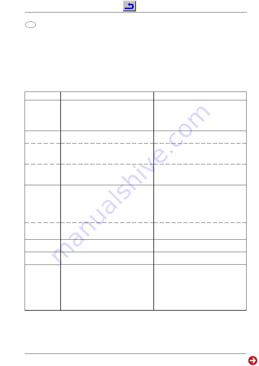
 Alignment

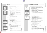
Start of the Service Mode: Via "

Ǻ

" (Dialog Center)  –> Service –> "OK" –> Service Code "8500".

End the Service Mode: Press button "TXT".

Measuring instruments: 100MHz oscilloscop with 10:1 test probe, digital voltmeter, colour video generator.

Service works after replacement or repair of the following modules:
- Power supply: 
alignment 1
- IF: alignment 2
- IC101 (Video IC), EEPROM: alignment 2
- CRT, CRT panel: alignment 6…8
- Deflection: alignment 7
- IC402: alignment 2…5 and 7…8

1. +B voltage

2. IF

B/G, D/K, I
Standard

SECAM L/L'
Standard

3. Tuner AGC

3.1  "2.AGC"

L/L' Standard

4. OSD

5. OEM

6. Screen grid

voltage

This voltage must be checked and re-adjusted if necessary
after every repair and before every alignment.

Brightness:

Minimum

Contrast:

Minimum

Digital voltmeter:

Cathode D607

Start the Service Mode; call up the dialog line "Video" via
menu 1 (red button) with button 

Ƕ

.

Feed in a standard signal of a TV station. Set fine tuning to
"00" and store it via "OK".
Start the Service Mode; call up the dialog line "AFT38" via
menu 4 (blue button) with button 

Ƕ

or 

ǵ

.

Feed in a standard signal of a TV station. Set fine tuning to
"00" and store it via "OK".
Start the Service Mode; call up the dialog line "AFT33" via
menu 4 (blue button) with button 

Ƕ

or 

ǵ

.

100MHz oscilloscope: Channel A: Tuner contact 11

Ground:

Tuner

Colour video generator:

Feed in a colour scale (with
switched-off sound carrier) via the
aerial: channel 32; 70

±

1dB

µ

V.

Start the Service Mode; call up the dialog line "AGC" via
menu 1 (red button) with button 

Ƕ

or 

ǵ

.

Call up the dialog line "2.AGC" with button 

Ƕ

or 

ǵ

.

Start the Service Mode; call up the dialog line "OSD.H" and
"OSD.V" via menu 2 (green button) with button 

Ƕ

or 

ǵ

.

Start the Service Mode; call up the dialog line "OEM" via
menu 1 (red button) with button 

Ƕ

or 

ǵ

.

Start the Service Mode; call up the dialog line "SCRN" via
menu 3 (yellow button) with  button 

Ƕ

or 

ǵ

.

Switch on the horizontal line with button 

Ǹ

 or 

Ƿ

.

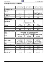
Adjust +B to the values below with P601:

Size

CRT

Voltage Value

14"

A34LPE02X01

106V

20"

A48ECR43X51

118V

21"

A51EER133X41

118V

With button 

Ƿ

 set to "NEW".

End the Service Mode.

With button 

Ǹ

 or 

Ƿ

 set the right Hex-value to 78-7C

(e.g.: AFT38 87 79).

End the Service Mode.

With button 

Ǹ

 or 

Ƿ

 set the right Hex-value to 78-7C

(e.g.: AFT33 87 79).

End the Service Mode.

With button 

Ǹ

 or 

Ƿ

 set to the following values:

PAL B/G standard

750mV

pp 

±

20mV

pp

PAL/SECAM B/G/D/K standard

750mV

pp 

±

20mV

pp

SECAM L/L' standard

600mV

pp 

±

20mV

pp

PAL I standard

700mV

pp 

±

20mV

pp

End the Service Mode.

With button 

Ǹ

 or 

Ƿ

 set the same value like AGC.

Example: AGC = 48 -> 2.AGC = 48
End the Service Mode.

With button 

Ǹ

 or 

Ƿ

 position the picture to the center of the

screen. End the Service Mode.

With button 

Ǹ

 or 

Ƿ

 set to "off".

End the Service Mode.

With "SCREEN" control (lower control at the splitter
transformer) adjust the line so that it is just well visible.

Alignment

Preparations

 Alignment Process

Summary of Contents for DAVIO 37 P 37-2201

Page 1: ...aire n cessaire pour la maintenance Additionally required Service Documents for the Complete Service Service Manual Service Training TV Service Manual Chassis 12 6 DAVIO 37 P 37 2201 FR GBA0502 DAVIO...

Page 2: ...Table of Contents Page General Section 1 3 1 12 General Notes 1 3 Safety Advice 1 3 Service Note 1 3 Tables of Norms and Channels 1 4 Technical Data 1 7 Operating Hints DAVIO 55 T55 4201 FR TOP only F...

Page 3: ...keyboard control panel picture tube panel deflection unit loudspeaker and so on On completion of the repairs the leads must be laid out as originally fitted at the factory to avoid later failures or d...

Page 4: ...50 C 51 703 25MHz 711 25MHz 52 53 54 55 C 52 C 53 719 25MHz 727 25MHz C 54 C 55 735 25MHz 743 25MHz 56 57 58 59 C 56 C 57 751 25MHz 759 25MHz C 58 C 59 767 25MHz 775 25MHz 60 61 62 63 C 60 C 61 783 2...

Page 5: ...Hz 380 75MHz Y S 62 392 75MHz Interbande Special Channels Norme L L Norm L L Ecart son image Sound vision spacing 6 5MHz Pas des canaux Channel bandwidth 10 5MHz Nom Name S 70 S 71 S 72 N canal Channe...

Page 6: ...dwidth 8MHz Nom Name S 21 S 22 S 23 N canal Channel no S 21 Fr quence image Vision carrier frequency 303 25MHz S 22 S 23 311 25MHz 319 25MHz S 24 S 25 S 26 S 27 S 24 S 25 327 25MHz 335 25MHz S 26 S 27...

Page 7: ...sung 90 50Hz 99 2 AV PLL fr quence synthesizer Tuning UHF VHF PLL frequency synthesizer tuning UHF VHF 99 2 AV B G L L PAL SECAM via AV NTSC 4 43MHz B G L L PAL SECAM via AV NTSC 4 43MHz Mono 5W ront...

Page 8: ...l Section 1 8 Mode d emploi Ce chapitre contient des extraits du mode d emploi Pour toutes informations suppl mentaires veuillez vous r f rer au mode d emploi sp cifique chaque appareil dont le num ro...

Page 9: ...GRUNDIG Service 1 9 Partie g n rale General Section Ch ssis Chassis 12 6...

Page 10: ...ALPS Version du tuner version of tuner PHILIPS P SONIC AGC TEMIC voir alignement see adjustment Version du tuner version of tuner Version du tuner version of tuner x Version du tuner version of tuner...

Page 11: ...nement see adjustment R DRV B DRV voir alignement see adjustment voir alignement see adjustment Menu 4 touche bleue button blue SCRN SECBL voir alignement see adjustment voir alignement see adjustment...

Page 12: ...usine par la touche Dialog Center Service OK R glages d usine puis m moriser par OK 8 Num ro de programme maximal point d inversion Lorsque la fonction ATS est termin e le point d inversion est ajout...

Page 13: ...teuse son d sactiv e via l antenne Canal 32 70 1dB V Activerlemodedeservice choisirlemenu1 touche rouge A l aide de ou s lectionner AGC A l aide de ou s lectionner 2 AGC Activer le mode de service cho...

Page 14: ...CUT A l aide de la touche ou s lectionner R CUT A l aide de la touche ou s lectionner B CUT A l aide de la touche ou s lectionner R DRV A l aide de la touche ou s lectionner B DRV Seulement n cessaire...

Page 15: ...nd Tuner Colour video generator Feed in a colour scale with switched off sound carrier via the aerial channel 32 70 1dB V Start the Service Mode call up the dialog line AGC via menu 1 red button with...

Page 16: ...with button or Only necessary if deadjusted Adjust according to the test pattern using button or Adjust according to the test pattern using button or Adjust according to the test pattern using button...

Page 17: ...lectriques Layout of PCBs and Circuit Diagrams GRUNDIG Service 3 1 TV marche on Standby TV marche on Standby m u i v x Oscillogrammes du ch ssis Oscillograms Chassis Board Circuit imprim s et sch mas...

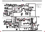
Page 18: ...Circuit imprim s et sch mas lectriques Layout of PCBs and Circuit Diagrams Ch ssis Chassis 12 6 3 2 GRUNDIG Service y u v x y m i v x y m u i v...

Page 19: ...ut of PCBs and Circuit Diagrams GRUNDIG Service Ch ssis Chassis 12 6 Circuit imprim s et sch mas lectriques Layout of PCBs and Circuit Diagrams 3 3 3 4 C I Ch ssis Principal Chassis Board C te composa...

Page 20: ...it Diagrams Ch ssis Chassis 12 6 GRUNDIG Service Circuit imprim s et sch mas lectriques Layout of PCBs and Circuit Diagrams Ch ssis Chassis 12 6 3 5 3 6 C I Ch ssis Principal Chassis Board C te soudur...

Page 21: ...0p 500V C517 H LIN L502 HORIZONTAL X502 4 3 2 1 FBT TR501 8 4 1 11 9 7 6 2 5 10 3 G2 FOCUS EHT 6 8n 1 5kV C513 9V R521 47u 35V C512 2 2uH L501 27R 0 5W R518 4 7k R519 BU808DFI T504 82R 3W R517 10k R51...

Page 22: ...SW402 SW401 1k R413 VDD_2 5V 1N4148 D404 10n C409 9V 47n C412 10k R419 2 2k R420 3 3V 1k R423 10k R418 BC848 T403 220p C413 1k R466 10n C414 10k R427 10k R433 10n C417 BC848 T404 BC848 T405 MULTIMEDIA...

Page 23: ...6 VERT_OUT 45 SAW TOOTH 44 AUD_ DECOUPLING 43 AFC1 42 HORIZ_OUT 41 H_VCC 6 3V 40 3 58 39 HOR_SYNC 38 VID_IN_SYNC 37 C APC2 36 VIDEO_OUT 35 VCC 4 7V 34 EXT_VIDEO_OUT 33 VCC 32 EXT_AUDIO_OUT 31 BLK LEVE...

Page 24: ...R720 220R opt R719 CRT X701 5 4 3 2 1 SMPS AQUA G2 CRT X703 3 2 1 155V crt 100n 250V C708 2 2n C707 1 5K R714 1 5K R708 1 5K R704 9V_ 9V_ 2 7k R716 crt 100R R718 390p C706 crt 470R R717 155V 15k 1W R7...

Page 25: ...0604 S 725511823600 DIODE RF2007 D 00606 S 725511823600 DIODE RF2007 D 00607 S 830956550700 DIODE RGP10J 1N4937 MOT G D 00609 S 759550453500 DIODE RGB15D D 00610 S 759880511100 DIODE RGP15J D 00701 83...

Page 26: ...nual Sicherheit Mat Nummer 720108000000 sowie zus tzlich die eventuell abwei chenden landesspezifischen Vorschriften II y a lieu d observer les recommandations et les prescriptions de s curit de I Ins...

Page 27: ...23600 DIODE RF2007 D 00606 S 725511823600 DIODE RF2007 D 00607 S 830956550700 DIODE RGP10J 1N4937 MOT G D 00609 S 759550453500 DIODE RGB15D D 00610 S 759550455400 DIODE RGP30MS D 00701 830921503300 DI...

Reviews: