background image

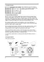
1. Available Versions

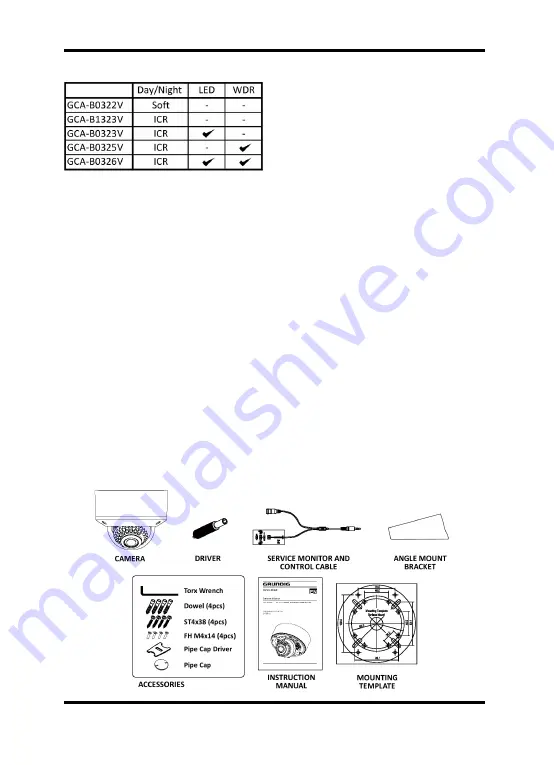
These instructions apply to the following 
products. For the different properties of the 
products please refer to the table.

2. Important Safety Instructions

Be sure to use only the standard adapter that is specified in the specification sheet. 
Using any other adapter could cause fire, electrical shock, or damage to the product. 
Incorrectly connecting the power supply or replacing battery may cause explosion, fire, 
electric shock, or damage to the product. Do not connect multiple products to one single 
adapter. Exceeding the capacity may cause abnormal heat generation or fire.

Do not place conductive objects (e.g. screwdrivers, coins or any metal items) or 
containers filled with water on top of the product. Doing so may cause personal injury 
due to fire, electric shock, or falling objects.

If any unusual smells or smoke comes from the unit, stop using the product. In such 
case, immediately disconnect the power source and contact the service center. 
Continued use in such a condition may cause fire or electric shock.

If this product fails to operate normally, contact the nearest service center. Never 
disassemble or modify this product in any way. (GRUNDIG is not liable for problems 
caused by unauthorised modifications or attempted repair.)

To prevent fire or electric shock, do not expose the inside of this device to rain or 
moisture.

3. Package Contents

These parts are included:

2

English

Summary of Contents for GCA-B0322V

Page 1: ...as Domes GCA B1323V 1 3 CCD Col B W Fixed Dome Camera GCA B0322V 1 3 CCD Col B W Fixed Dome Camera GCA B0323V 1 3 CCD Col B W Fixed Dome Camera w IR LED GCA B0325V 1 3 CCD Col B W Fixed Dome Camera WDR GCA B0326V 1 3 CCD Col B W Fixed Dome Camera IR LED WDR ...

Page 2: ......

Page 3: ...tion 4 3 Angle Mount Bracket Advantage 5 4 Mounting Housings to Electrical Junction Boxes 5 5 Connections 6 6 3 Axis Gimbal Adjustment 6 7 Zoom Focus Adjustment 7 5 OSD Menu 7 1 OSD Controls 7 2 Main menu 8 3 Camera Setup 9 4 Intelligence 16 5 Privacy Zone 18 6 Other Set 19 7 Communication 19 8 System Info 19 9 Language 20 1 English ...

Page 4: ...t place conductive objects e g screwdrivers coins or any metal items or containers filled with water on top of the product Doing so may cause personal injury due to fire electric shock or falling objects If any unusual smells or smoke comes from the unit stop using the product In such case immediately disconnect the power source and contact the service center Continued use in such a condition may ...

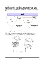
Page 5: ...sooty locations Doing so may cause fire or electric shock Install it in a place with good ventilation When installing the unit fasten it securely and firmly A falling unit may cause personal injury If you want to relocate the already installed product be sure to turn off the power and then move or reinstall it 4 1 Part Names 1 Bubble 2 Dome Cover Ring 3 Lens 4 Service Monitor Output Port 5 Flush M...

Page 6: ...urface Mount Using the four ST4x38 screws mount the surface plate to a sturdy surface Using the four M4x14 screws affix the flush mount base to a surface plate For flush mount application disregard section 2 3 Flush Mount Using the four ST4x38screws affix the flush mount base to a sturdy surface 4 English ...

Page 7: ...e wall surface supporting the camera It is ideal for monitoring ATMs entrances display cases etc 4 4 Mounting Housings to Electrical Junction Boxes This unit can be either flush mounted or surface mounted with Electrical Junction Boxes using the pre drilled mounting holes The dome housing accommodates various electrical junction boxes making the installation easy and less time consuming 5 English ...

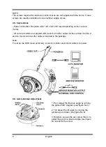
Page 8: ...ce monitor output on the camera module A service monitor and control cable is included in the package Note To set up the OSD menu externally a service monitor and control cable is required 4 6 3 Axis Gimbal Adjustment 1 Pan Adjust the first pan angle by turning the gimbal 360 degrees see figure No 1 2 Tilt Adjust the tilt angle by moving the gimbal up and down see figure No 2 3 Rotation Loosen the...

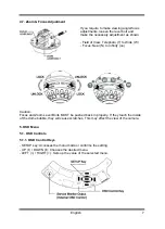
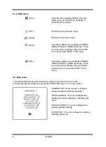
Page 9: ... N to Infinity oo Caution Focus and Zoom Lever Bolts MUST be pushed back in properly If they touch the inside of the dome bubble they will cause scratches This may effect the view of the camera 5 OSD Menu 5 1 OSD Controls 5 1 1 OSD Control Keys SETUP key Accesses the menu mode or confirms the setting UP DOWN Chooses the desired menu LEFT RIGHT Sets up the value of the selected menu 7 English ...

Page 10: ...ASK AREA PRIVACY ZONE and more Once you saved your settings they will not be restored even if you select QUIT in the menu 5 2 Main menu 1 Press the SETUP key and hold it for a while to access the menu mode 2 Select the desired feature by using the UP DOWN keys on the control CAMERA SET Here you can configure camera related functions and data INTELLIGENCE You can configure the settings of motion de...

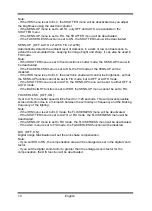
Page 11: ...cts in the same lighting condition Note This is only available if the SENS UP menu is set to AUTO If the DAY NIGHT menu of CAMERA SET is set to AUTO the MOTION menu will be deactivated DNR OFF LOW MID HIGH USER 1 16 You can configure the DNR Digital Noise Reduction related settings It reduces the noise on the screen This is especially useful for a severely distorted screen You can set the level if...

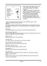
Page 12: ...nnot be set to FIX mode but to OFF or AUTO mode If the SHUTTER menu is set to AUTO the SENS UP menu can be set to either OFF or AUTO mode If the BACKLIGHT function is set to WDR the SENS UP menu cannot be set to FIX FLICKERLESS OFF ON If set to ON the shutter speed will be fixed to 1 120 seconds This will prevent possible screen distortion due to a mismatch between the vertical sync frequency and ...

Page 13: ...DAY NIGHT menu setting EXT to get the best results WHITE BAL If you want to adjust the colour scheme use the WHITE BALANCE function DIGITAL ZOOM ON OFF You can set the digital zoom factor and position When the zoom factor and position are defined the digital zoom function will operate DETAIL 0 3 Controls the horizontal or vertical distinction V SYNC INT This camera model is set to fixed INT Intern...

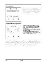
Page 14: ...e LENS option you must select DC for this camera model In the LEVEL option you can adjust the overall brightness where will increase the brightness and will decrease it In the BACKLIGHT option you can adjust the BLC Back Light Compensation function You can set the desired BLC zone by defining the size and the location If you use the ordinary camera in a scene with an intensive back light the objec...

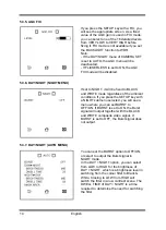
Page 15: ...ewing near a window or door entrance It improves the sharpness of the picture of the outside view as well as indoor view WDR is only available for GCA B0325V and GCA B0326V 5 3 3 ELC Electronic Light Control If you press the SETUP key when the ELC submenu is selected the corresponding screen appears You can set the ELC function to active or not Similar to the ALC setting you can specify the BLC ar...

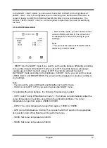
Page 16: ...mbient conditions If you press the SETUP key with a NIGHT submenu selected you will see a menu where you can set BURST to OFF ON If BURST is set to ON the Burst signal will output together with the BLACK and WHITE composite video signal If BURST is set to OFF the Burst signal does not output 5 3 7 DAY NIGHT AUTO MENU You can set the BURST option to OFF ON or select to output the Burst signal in NI...

Page 17: ...s set in DAY mode if not set to OFF the camera will switch as set in DAY NIGHT mode according to the brightness In NIGHT mode you can set the values of RED BLUE and BRIGHTNESS The screen will be displayed in colours according to your settings Note You can set the values of R GAIN and B GAIN only in AWC mode If AGC is set to OFF or FIX you cannot access the NIGHT menu For adjusting the white balanc...

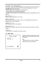
Page 18: ...osition are defined the digital zoom function will operate RATIO Define the zoom factor with the direction keys LOCATION If you press the SETUP key you can change the position of the digital zoom with the direction keys Note The DIGITAL ZOOM function enlarges the pixel itself which can cause deterioration of the image quality 5 4 Intelligence MOTION OFF TRACKING DETECTION TRACKING Detects and trac...

Page 19: ...GCA B0325V and GCA B0326V MASK AREA 1 4 Specify a detection exception area to mask DISPLAY ON OFF With the DISPLAY option set to ON a motion or a set ADVANCED function will be displayed on the screen if detected SENSITIVITY 1 7 Set the sensitivity of the motion detection RESOLUTION 1 5 If you set the resolution to high the camera can even detect movements of very small objects ALARM OUT This funct...

Page 20: ...el that moves as you change the PIXEL LEVEL to set the position How to set a point You can set each position of the 4 points If you press the SETUP key in POINT you will see the points available in the PRIVACY ZONE Each time you press the SETUP key the accessed point will change Use the four direction keys to set the position of each point Set each position of the four points and press the SETUP k...

Page 21: ...ault OSD COLOR BW R G B You can set the OSD On Screen Display colour to BW RED GREEN and BLUE 5 7 Communication Configure the settings regarding the UART communication This function is not available in this camera version 5 8 System Info You can view the system information in this menu including the type protocol address baud rate serial number and camera version 19 English ...

Page 22: ...5 9 Language The camera supports 5 different languages Select your preferred language from the list 20 English ...

Page 23: ...nes 8 polygonal method High Speed Shutter 1 50 1 10 000 sec auto BLC On Off Area Level AGC Off On Very LOW LOW Mid High Very High User Fix Digital Noise Reduction DNR Off On Low Middle High User Digital Zoom Off 1 10x Digital Image Stabilization DIS Off On PIP On Off Reverse Off H REV V REV HV REV POSITIV NEGATIV Intelligent Video Analytics Tracking Detection OSD Yes EN FR DE SP IT Camera ID 54 ch...

Page 24: ... 126 mm Dimensions wxhxd Specifications GCA B0325V Image Sensor 1 3 CCD Sony PS Super HAD with WDR Sensitivity B W 0 04 lux 50IRE f1 2 0 0001 lux sens up 256x BLC On Off Area Level WDR Wide Dynamic Range On Off extreme backlight compensation WDR x160 2 4 W Power Consumption 1 12 kg Weight Ø 152 x 126 mm Dimensions wxhxd Specifications GCA B0326V Image Sensor 1 3 CCD Sony PS Super HAD with WDR Sens...

Page 25: ...Dimensions 23 English ...

Page 26: ... Dome Camera IR LED WDR It is hereby certified that the products meet the standards in the following relevant provisions EC EMC Directive 2004 108 EC Low Voltage Directive 2006 95 EC Applied harmonised standards and technical specifications EN 55022 2006 Class A EN 50130 4 1995 A1 1998 A2 2003 EN 61000 3 2 2006 EN 61000 3 3 1995 A1 2001 A2 2005 Ludwig Bergschneider CEO Remscheid 29 11 2011 ASP AG ...

Reviews: