background image

Content:

1. Introduction

1

2. Important Safety Instructions

1

3. Package Contents

2

4. Installation

2

1. Installation Remarks

                                     2

2. Switch & Connector Definition

                     3

3. Communication Switch Setting

                    4

4. ID Configuration

4

5. Camera Control Protocol Setup

                  7

6. Power Connection

5

7. Alarm Application

6

8. RS-485 Connector Definition

6

5. Operation and Configuration

7

1. OSD Display Format

7

2. OSD Menu Tree

                                              8

3. Configuration Menu

                                     10

6. Switch Settings Index Table

30

1. Introduction

Based on the Television Standard for Full HD Television, HD-SDI products feature 2 Megapixel (1920x1080) 
pictures in real-time (30fps) transmitted over coax cabling.
Get the advantages of an IP technology without their drawbacks. Get 16:9 megapixel pictures without network 
configuration, bandwidth problems and network security risks. Use existing coax cables and only exchange the 
cameras and recorders. Get a “real” live picture and see the things that happen in the now, not a few seconds 
later. Connect a monitor directly to a camera using only a HD-SDI-to-HDMI converter. 
HD-SDI products are easy to handle, easy to install and produce amazing high quality pictures.

Combing the HD-SDI standard with a high quality SONY CMOS sensor, the HD-SDI High Speed Camera delivers 
up to 18x optical zoom ratio to capture a clear image in the distance. Continuous Auto Focus, Back Light 
Compensation and Auto Exposure functions are provided for clear and high quality images. A removable IR cut 
filter ensures 24 hours operation, while Privacy Masks are especially designed to avoid any intrusive monitoring 
at specific regions. All of the salient functions can be incorporated to meet your needs. The Home function allows 
users to specify a preset position as the ‘home position’ or home functions (Sequence/Auto-pan/Cruise). Under 
this mode, HD-SDI Motordome Cameras can come back to the preset home position or functions when the 
camera has been idle for a user-defined period of time. Additionally, the unique Schedule function enables users 
to program a preset point or function (Sequence/Auto-pan/Cruise) so that these actions can be automatically 
performed in a certain period of time.

The HD-SDI Motordome Camera provides variable pan/tilt speeds ranging from a fast patrol of 90° per second to 
a slow ramble of 0.5° per second with 0.225° pan/tilt accuracy for fast and accurate tracking ability. The 360° 
endless rotation and -10°~190° tilt travel make tracking the object passing directly beneath the dome possible. A 
maximum of 256 preset points can be programmed for precise location of target areas, and users can also define 
Sequence lines, Auto-Pan lines and Cruise routes for the camera to operate automatically. In addition, the RS-
485 communication port is available for remote control purposes.

2. Important Safety Instructions

Be sure to use only the standard adapter that is specified in the specification sheet. Using any other adapter 
could cause fire, electrical shock, or damage to the product. Incorrectly connecting the power supply may cause 
explosion, fire, electric shock, or damage to the product. Do not connect multiple products to one single adapter. 
Exceeding the capacity may cause abnormal heat generation or fire.

Do not place conductive objects (e.g. screwdrivers, coins or any metal items) or containers filled with water on 
top of the product. Doing so may cause personal injury due to fire, electric shock, or falling objects.

If any unusual smells or smoke comes out of the unit, stop using the product. In this case, immediately 
disconnect the power source and contact the service center. Continued use in such a condition may cause fire or 
electric shock.

1

English

Summary of Contents for GCH-K0274P

Page 1: ...GCH K0274P 41 1 20 01 2012 Owner s Manual ASP AG HD SDI Cameras Domes GCH K0274P 2 Megapixel Full HD Outdoor Motorised Dome SDI Camera 18x Zoom ICR WDR ...

Page 2: ......

Page 3: ... home position or home functions Sequence Auto pan Cruise Under this mode HD SDI Motordome Cameras can come back to the preset home position or functions when the camera has been idle for a user defined period of time Additionally the unique Schedule function enables users to program a preset point or function Sequence Auto pan Cruise so that these actions can be automatically performed in a certa...

Page 4: ...product in a location subject to high temperature over 50 C low temperature below 10 C or high humidity Doing so may cause fire or electric shock Keep out of direct sunlight and heat radiation sources This may cause fire Avoid aiming the camera directly towards extremely bright objects such as the sun as this may damage the image sensor Do not install the unit in humid dusty or sooty locations Doi...

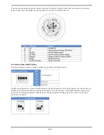
Page 5: ... Dome Camera to other devices of a CCTV system please complete first the Dome Camera s ID and communication switch settings These switches are located on the bottom of the Dome Camera Additionally the 22 Pin Connector for Data Cable connection and the ISP Connector for firmware upgrade kit connection are located on the back plate of the analogue Swiftdome Camera 3 English ...

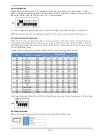
Page 6: ...Dome Camera s communication switches are specified in the table below RS 485 is the interface for communication between the Dome Camera and its control device For this reason the RS 485 setup of the Dome Camera and the control device must be the same The RS 485 default setting is half duplex see the following diagram Please do not change the default setting without the notice of a qualified specia...

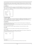
Page 7: ... Camera Control Protocol Setup Define the protocol you are going to use based on the devices of your surveillance system Generally the use of one protocol is recommended even if the devices are provided from different manufacturers Please refer to the table below for all supported protocols with their matching switch numbers and baud rate and choose a protocol for your Motordome Camera The table b...

Page 8: ...ake sure the alarm connections are properly wired before starting to configure the alarm related settings Please refer to the pin definition table below for alarm system wiring 4 8 RS 485 Connector Definition Please refer to the illustrations below for RS485 connector definition before wiring 6 English ...

Page 9: ...5 Operation and Configuration 5 1 OSD Display Format Regarding information about the OSD display position and function description please refer to the table below 7 English ...

Page 10: ...OSD Menu Tree The OSD setup menu structure is listed in the following section The star symbol indicates the factory default For detailed function description please refer to 5 3 Configuration Menu 8 English ...

Page 11: ...9 English ...

Page 12: ...sed protocol To select a setup item use the direction keys on the keyboard to move the OSD cursor in the OSD menu To set up items use the direction keys on a keyboard to move the OSD cursor in the OSD menu For items with ENTER press the CAMERA MENU key on the control keyboard to enter their sub menus For other items users can use the right left direction key to select the functions and then press ...

Page 13: ...cus Exposure Compensation AE WBC Aperture Noise Reduction IR Function and WDR Once any one of the items is modified the setting will become OFF automatically Select ON for this item to recall the mentioned camera parameters 5 3 3 BACKLIGHT The Backlight Compensation function prevents the centre object from being too dark in surroundings where excessive light is behind the centre object When you se...

Page 14: ...trol control circuits work together automatically to get consistent video output level SHUTTER With this option the Shutter speed takes main control of exposure Bright Value Iris and AGC will function automatically in cooperation with the shutter speed to achieve a consistent exposure output The range of shutter speed starts from 1 10000 to 1 25 at PAL systems NTSC 1 10000 to 1 30 IRIS With this o...

Page 15: ... 2 500 to 3 000 K 75 watt Bulb Colour Temperature 2 820 K Candle Flame Colour Temperature 1 200 to 1 500 K AUTO In this mode white balance works within its colour temperature range This mode computes the white balance value output using the colour information from the entire screen It outputs the proper value using the colour temperature radiating from a black subject based on a range of values fr...

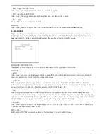
Page 16: ...n in low light conditions IMAGE INVERSE Users can select ON to make the displayed image inversed vertically and horizontally Occasions to employ the function include conferences demonstration testing etc The default setting is OFF Application Users can see the displayed images when a dome is placed on top of a desk for instance APERTURE Users can adjust the enhancement of the edges of objects in t...

Page 17: ...e Dome Camera tilts to the maximum angle it will pan 180 and then continue tilting to keep tracking objects OFF Select this item to disable the flip function EXIT SET Exit the FLIP Setting menu and go back to SETUP MENU 2 to set other functions NOTE To make the Dome Camera tilt between a specific range such as 10 to 100 please go to ANGLE ADJUSTER see next section to set the angle range of the til...

Page 18: ... 90 After lower than 90 the PAN degree will be automatically added 180 Press TO SAVE to save the pan zero setting EXIT SET Exit the PT POSITION menu and go back to SETUP MENU 2 to set other functions SPEED BY ZOOM If this item is set to ON the pan tilt speed will be adjusted by an internal algorithm when zooming automatically A larger zoom ratio leads to a lower rotation speed AUTO CALI Auto Calib...

Page 19: ...A MENU to exit the password setting page If the OSD Password function is enabled and you press the CAMERA MENU key to enter the OSD menu the password request message will be displayed as shown below Please enter the password press ENTER to access the OSD main menu NOTE When you activate the Password Function for the first time please enter first the following Master Password to be allowed to setup...

Page 20: ...hapter 4 4 ID Configuration ON Display the ID of the selected dome at the right bottom of the monitor screen OFF Hide the ID of the selected dome 5 3 10 TITLE DISPLAY Users are allowed to name a certain view area and display its title for easy recognition With this item users can choose to display or not to display the titles set in advance ON A title set for a certain view will be displayed when ...

Page 21: ... back to MAIN PAGE 2 to set up preset points 5 3 12 PRESET STEP 1 Press the RIGHT LEFT direction key on the keyboard to select a number 1 represents Preset Point 1 2 represents Preset Point 2 etc PRESET SET In total 256 preset points can be set Follow the steps below in the preset setting menu STEP 2 Press the CAMERA MENU key ENTER on the keyboard and then rotate the dome camera to a target shooti...

Page 22: ...ss than 64 points NOTE If you are not using all 64 points please set the point following the last Sequence Point as END PRESET POSITION so that the sequence line can work properly For example if a user intends to set a Sequence Line with 5 sequence points It is required to set the PRESET POSITION of Sequence Point 06 as END SPEED Users can set the pan tilt speed of the Dome Camera from one Sequenc...

Page 23: ... the position as the start point the cursor will move to END POINT automatically Make sure to set the end point to complete the Auto Pan setting NOTE The tilt and zoom values of the start point will be recorded and fixed for the selected Auto Pan line END POINT Users are able to set the end point after the start point is defined Pan the Dome Camera to another position and press ENTER to save the p...

Page 24: ... RECORD START Follow the description below to record a CRUISE path STEP 1 Rotate the Dome Camera to a desired view area for some protocols users may need to do it before entering the OSD menu and press ENTER to perform a cruise path using the joystick on the control device The already used up percentage of the memory buffer will be displayed on the screen STEP 2 Pan and tilt the Dome Camera to for...

Page 25: ...to which the Dome Camera should go after the Return Time function which will be explained later is activated The preset point s should be set in advance either in the PRESET setup menu or through the keyboard SEQUENCE LINE Select a Sequence Line that the Dome Camera should execute when an alarm is triggered The Sequence Line s should be defined in advance in the SEQUENCE setup menu AUTOPAN LINE Se...

Page 26: ...hold indicates a higher sensitivity and can improve reliability of the lens so that it is easier to switch to Day mode and relatively difficult to change into Night mode While HI indicates that it is easier to switch to Night mode and difficult to change into Day mode MANUAL IR MANUAL ON Select the item to remove the IR cut filter The camera will change to B W Night mode IR MANUAL OFF Select the i...

Page 27: ...of the control keyboard to select a particular action mode The items listed below will change according to your selected alarm action Additionally when an alarm is triggered there the flash warning notice ALARM will be displayed in the upper right corner of the screen NOTE After an alarm condition Dwell Time Setting 1 127 seconds ALWAYS was released the Dome Camera will go back to the previous sta...

Page 28: ...rity of being handled The default alarm priority is 1 ALARM OUTPUT Here you can define which Alarm Out output will be triggered when an event happened OFF Both outputs are disabled 1 The output no 1 will be triggered 2 The output no 2 will be triggered BOTH Both outputs will be triggered EXIT Exit the ALARM SETTING menu and go back to MAIN PAGE3 to carry on with other setups 5 3 19 WDR FUNCTION Th...

Page 29: ...colour of a privacy mask can be set as transparent Select ON to display transparent masks COLOR The colour of a privacy mask can be set through this item The available colours are black white red green blue cyan yellow and magenta SET MASK Use the control device to move the Dome Camera to the area where you want to set a mask Press ENTER to enter the mask setting menu The dome will memorise the pr...

Page 30: ...sk zone that is to be erased e g 01 STEP 2 Press ENTER to confirm your selection EXIT Exit the PRIVACY MASK menu and go back to MAIN PAGE 3 to carry on with the time related setup 5 3 21 TIME SETTING The time setting function is used to set the TIME related parameters of the Motordome Camera Each item in the menu is listed as follows TIME DISPLAY Select ON to display Time information on the screen...

Page 31: ... as follows NONE No action will be executed for the schedule if this item is selected PRESET Users can select the PRESET mode as an action carried out in a schedule point SEQUENCE Users can select the SEQUENCE mode as an action carried out in a schedule point AUTOPAN Users can select the AUTOPAN mode as an action carried out in a schedule point CRUISE Users can select the CRUISE mode as an action ...

Page 32: ...6 Switch Settings Index Table Please refer to the switch settings below for the Dome Camera s ID and protocol setup 30 English ...

Page 33: ...31 English ...

Page 34: ...32 English ...

Page 35: ...33 English ...

Page 36: ...34 English ...

Page 37: ...35 English ...

Page 38: ...36 English ...

Page 39: ...ange 360 Endless Tilt Range 10 190 Pan Speed Manual 0 5 s 90 s Preset 400 s max Tilt Speed Manual 0 5 s 90 s Preset 400 s max Range Panning 360 endless Presets 256 PTZ Control Pan Tilt speed proportional to Zoom ratio On Off Protocol Pelco D Pelco P Serial Interface s RS 485 PTZ Control Auto PAN Preset Sequence and Cruise Function Support Alarm Inputs 4 Alarm Outputs 2 OSD Yes Number of Privacy Zo...

Page 40: ...6 95 EC Applied harmonised standards and technical specifications EN 55022 2006 A1 2007 Class A IEC EN 61000 3 2 2006 A2 2009 IEC EN 61000 3 3 2008 AS NZS CISPR22 2009 Class A EN 50130 4 1995 A1 1998 A2 2003 IEC 61000 4 2 2008 IEC 61000 4 3 2010 IEC 61000 4 4 2010 IEC 61000 4 5 2005 IEC 61000 4 6 2008 IEC 61000 4 11 2004 Mains Supply Voltage Variations Ludwig Bergschneider CEO Remscheid 13 03 2012...

Reviews: