background image

Vertiga UMS 5100

Abgleichvorschriften / Adjustment Procedures

GRUNDIG Service

2 - 1

Abgleichvorschriften

Tuner

Messgeräte:

 Wobbel- / Mess-Sender, Klirrfaktormessgerät, Oszilloskop, Digital-Voltmeter

Hinweis:

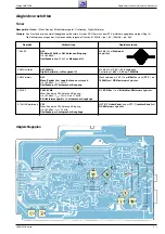
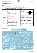
Das Frontend ist ein komplett abgeglichener Baustein. Nur das ZF-Filter muss dem ZF-Verstärker angeglichen werden (Abgl. 4).
Die Abstimmspannungen des Frontends haben folgende Grössen: 87,5MHz = typ. 1,6V; 108MHz = typ. 8,0V.

Abgleich

Vorbereitung

 Abgleichvorgang

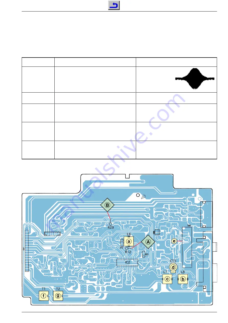
1. AM-ZF

2. AM-Oszillator

3. AM-Vorkreis

4. FM-ZF

5. 19kHz-Sperrkreise

AM

;

Wobbler 450kHz 

an 

AM-Antennen-Eingang

;

Ue > 60dB

µ

V;

Oszilloskop 

über 100nF an 

Messpunkt 

A

.

AM

,

 522kHz

;

Digital-Voltmeter

 an 

Messpunkt


B

.

AM

;

Mess-Sender

 über 

Loop-Antennen

 ankoppeln;

Ue > 50dB

µ

V; f

mod

 = 1kHz;

Oszilloskop 

an 

Lautsprecher-Ausgang

.

FM, 98,1Mz

;

Mess-Sender an FM-Antennen-Eingang;
Ue = 20dB

µ

V; f

mod

 = 1kHz; Hub = 75kHz;

Klirrfaktormessgerät 

an 

Lautsprecher-Ausgänge

.

FM

;

Mess-Sender an FM-Antennen-Eingang;
Ue = 50dB

µ

V; f

mod

 = 19kHz;

Oszilloskop 

an 

Lautsprecher-Ausgänge

.

Mit 

L6 

a

 auf 

Maximum

abgleichen.

Mit 

L8 

b

 auf 

1,4V 

±

 0,1V

 abgleichen.

Kontrolle auf 

8,0V 

±

 0,2V

 bei 

1620MHz

.

Wechselweise mit 

L7 

c

 bei 

612kHz 

und mit 

CT3 

d

 bei

1404kHz 

auf 

NF-Maximum

 abgleichen.

Mit 

ZF-Filter 

e

 auf 

Klirrfaktor-Minimum

 abgleichen.

Mit 

T2 

g

 (

linker Kanal

)


und mit 

T1 

f

 (

rechter Kanal

)


auf

NF-Minimum

 abgleichen.

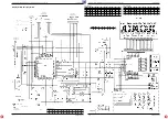
Abgleichlageplan

Summary of Contents for GLL0252

Page 1: ...180 52318 42 0180 52318 43 0180 52318 44 0180 52318 45 0180 52318 51 0180 52318 99 Mo Fr 8 00 18 00 Uhr Telefon 0180 52318 40 0180 52318 50 Fax Technik Ersatzteil Verkauf Mo Fr 8 00 19 00 Uhr Kundendi...

Page 2: ...and Spare Parts List 4 1 4 4 Inhaltsverzeichnis Seite Allgemeiner Teil 1 2 1 8 Messger te Messmittel 1 2 Technische Daten 1 3 Servicehinweise 1 3 Ausbauhinweise 1 4 Bedienhinweise 1 6 Abgleichvorschr...

Page 3: ...ESET button on the bottom of the set using a small screw driver or a paper clip This will delete all stored settings Technische Daten Verst rkerteil Ausgangsleistung Sinusleistung 2 x 8W Musikleistung...

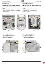
Page 4: ...rve the way they are routed On completion of the repairs the leads must be laid out as originally fitted at the factory 1 Cabinet Undo 7 screws A Fig 1 and 2 screws C Fig 2 Pull off the back panel B U...

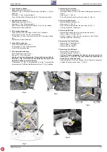
Page 5: ...urch statische Aufladung zerst rt werden 4 Schrauben S Fig 9 herausdrehen und die CD Leiterplatte herausnehmen BeiBedarfdieMotoranschl sseT Fig 9 abl ten 3 Removing Tuner Board Remove bottom plate par...

Page 6: ...Bedienelemente an der Oberseite TIMER SNOOZE Zum Einstellen des Einschalt Timers unterbricht das Wecken f r ca 5 Min CLOCK Zum Einstellen der Uhrzeit SLEEP Zum Einstellen des Sleep Timers X BASS Zum A...

Page 7: ...as CD Fach ge ffnet oder die Sicherheitsverriegelung berbr ckt wird Nicht dem Strahl aussetzen OPTICAL DIGITAL OUT SPEAKERS IMPEDANCE MIN 4 LINE IN AUX LINE OUT R R L L ANTENNA COA XIAL 75 AM LOOP AM...

Page 8: ...r cken w hlt einen Titel an l ngeres Dr cken sucht eine bestimmten Passage Im CD Betrieb beendet die Wiedergabe der CD VOLUME ndert die Lautst rke TIMER SNOOZE CLOCK 1 2 3 4 5 6 7 8 9 10 SLEEP 0 REPEA...

Page 9: ...cket for the rooftop antenna EXT or the wire antenna supplied ANTENNA AM Antenna terminals for the wire antenna EXT supplied OPTICAL Digital output for copying a CD onto a DIGITAL OUT digital recordin...

Page 10: ...e selects the RDS time RDS In tuner mode selects the RDS mode DISPLAY In tuner mode calls up various information on the display TIMER SNOOZE CLOCK 1 2 3 4 5 6 7 8 9 10 SLEEP 0 REPEAT STEREO MONO RANDO...

Page 11: ...Eingang Ue 60dB V Oszilloskop ber 100nF an Messpunkt A AM 522kHz Digital Voltmeter an Messpunkt B AM Mess Sender ber Loop Antennen ankoppeln Ue 50dB V fmod 1kHz Oszilloskop an Lautsprecher Ausgang FM...

Page 12: ...o AM Aerial Input Ue 60dB V Oscilloscope via 100nF to Testpoint A AM 522kHz Digital Voltmeter to Testpoint B AM Couple Signal Generator via Loop Antennas Ue 50dB V fmod 1kHz Oscilloscope to Loudspreak...

Page 13: ...en Circuit Diagrams and Layout of the PCBs Vertiga UMS 5100 Schaltpl ne und Platinenabbildungen Circuit Diagrams and Layout of the PCBs 3 2 3 1 Schaltpl ne und Platinenabbildungen Circuit Diagrams and...

Page 14: ...Tuner Platte Tuner Board IC2 LA1832 PIN 1 2 3 4 5 6 7 8 9 10 11 12 FM 2 11 4 94 2 11 2 1 0 02 4 99 4 93 2 81 4 95 0 3 79 3 79 AM 2 11 4 95 2 1 2 09 0 4 95 0 3 71 4 96 0 02 1 6 0 79 PIN 13 14 15 16 17...

Page 15: ...Vertiga UMS 5100 Schaltpl ne und Platinenabbildungen Circuit Diagrams and Layout of the PCBs Vertiga UMS 5100 Schaltpl ne und Platinenabbildungen Circuit Diagrams and Layout of the PCBs 3 6 3 5 Tuner...

Page 16: ...e 3 16 IC201 LA4725A PIN 1 2 3 4 5 6 7 8 9 10 11 12 1 49 5 5 0 3 2 2 32 1 47 2 1 5 18 5 16 0 5 15 0 PIN 13 14 5 05 11 8 IC202 BH3856S PIN 1 2 3 7 8 9 10 11 12 13 14 15 16 0 3 53 3 5 3 52 3 48 7 08 3 8...

Page 17: ...ne und Platinenabbildungen Circuit Diagrams and Layout of the PCBs Vertiga UMS 5100 Schaltpl ne und Platinenabbildungen Circuit Diagrams and Layout of the PCBs 3 10 3 9 Haupt Platte Main Board Netzte...

Page 18: ...2 4 0 2 4 0 2 57 2 7 2 42 2 4 2 45 PIN 59 60 61 62 80 0 2 52 2 5 2 4 IC802 MN151634 PIN 1 6 7 10 11 12 14 15 18 19 20 21 22 23 24 25 26 5 0 5 03 0 5 0 0 0 5 01 5 45 1 64 5 03 PIN 27 28 29 30 31 32 33...

Page 19: ...nabbildungen Circuit Diagrams and Layout of the PCBs Vertiga UMS 5100 Schaltpl ne und Platinenabbildungen Circuit Diagrams and Layout of the PCBs 3 14 3 13 Display Platte Display Board LED Platte LED...

Page 20: ...02 0 02 0 01 0 23 5 02 2 35 2 45 2 38 4 79 2 36 PIN 25 26 27 34 35 36 37 38 39 40 41 42 43 0 0 2 37 0 0 4 7 0 0 03 0 03 0 02 4 88 0 02 PIN 44 45 46 47 48 49 50 51 52 53 54 55 2 44 1 34 0 01 2 43 0 68...

Page 21: ...altpl ne und Platinenabbildungen Circuit Diagrams and Layout of the PCBs Vertiga UMS 5100 Schaltpl ne und Platinenabbildungen Circuit Diagrams and Layout of the PCBs 3 18 3 17 CD Platte CD Board IC403...

Page 22: ...g und Ersatzteilliste Exploded View and Spare Parts List Vertiga UMS 5100 Explosionszeichnung und Ersatzteilliste Exploded View and Spare Parts List Vertiga UMS 5100 Explosionszeichnung und Ersatzteil...

Page 23: ...DE 1 N 4001 GA D 00209 830921504500 DIODE 1N4148 AV619 GA D 00210 830921504500 DIODE 1N4148 AV619 GA D 00212 830921504500 DIODE 1N4148 AV619 GA D 00212 830921540100 DIODE 1N5401G GI FAG AV6 NETZTEIL P...

Page 24: ...SW 00007 759550489200 TAKTSCHALTER RS 014RB SW 00008 759550489200 TAKTSCHALTER RS 014RB SW 00009 759550489200 TAKTSCHALTER RS 014RB SW 00010 759550489200 TAKTSCHALTER RS 014RB SW 00011 759550324300 MI...

Reviews: