Vertiga UMS 5100
Allgemeiner Teil / General Section
GRUNDIG Service
1 - 5
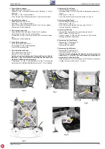
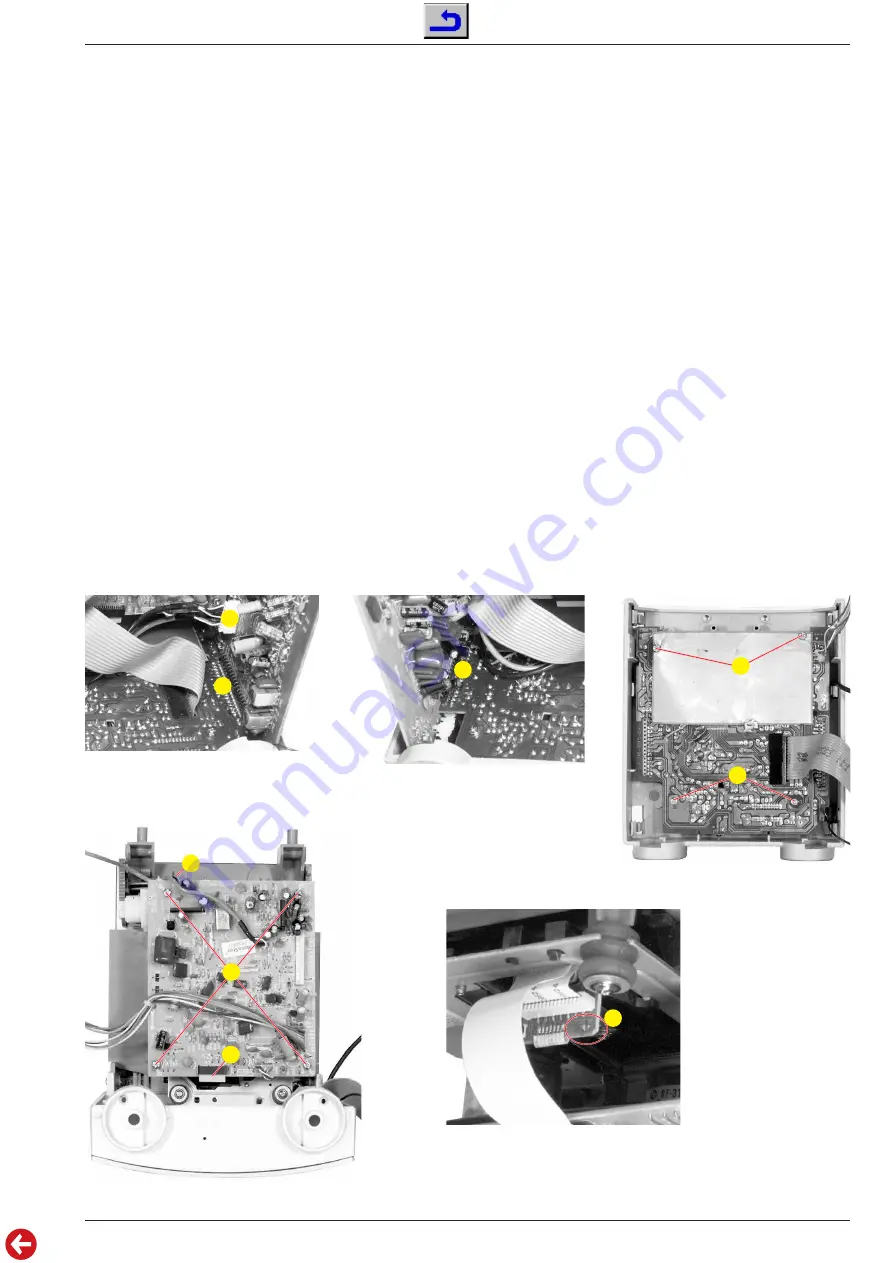
3. Tuner-Platte ausbauen
- Bodenplatte ausbauen (Pkt. 2).
- Stecker
H
(Fig. 4, unter der Abschirmung) und Stecker
I
(Fig. 6)
abziehen.
- Schraube
J
(Fig. 4) herausdrehen.
- Tuner-Platte aus dem Steckverbinder
K
(Fig. 6) herausziehen.
4. Haupt-Platte ausbauen
- Bodenplatte ausbauen (Pkt. 2).
- Schraube
L
(Fig. 3) herausdrehen.
- Haupt-Platte aus dem Steckverbinder
M
(Fig. 7) herausziehen.
- Stecker nach Bedarf abziehen.
5. CD-Laufwerk ausbauen
- Tuner-Platte (Pkt. 3) und Haupt-Platte (Pkt. 4) ausbauen.
- 2 Schrauben
N
(Fig. 4 und 5) herausdrehen.
- 2 Rastnasen
O
(Fig. 4 und 5) ausrasten und CD-Laufwerk abneh-
men.
- Stecker nach Bedarf abziehen.
6. Front-Platte ausbauen
- CD-Laufwerk ausbauen (Pkt. 5).
- 4 Schrauben
P
(Fig. 8) herausdrehen.
- Front-Platte herausnehmen.
7. CD-Leiterplatte ausbauen
- CD-Laufwerk ausbauen (Pkt. 5).
- Flexprint
Q
(Fig. 9) abziehen.
Achtung: Vor dem Abziehen der Flexprintleitung die Schutz-
lötstelle
R
(Fig. 10) zulöten! Die Laserdiode kann sonst durch
statische Aufladung zerstört werden.
- 4 Schrauben
S
(Fig. 9) herausdrehen und die CD-Leiterplatte
herausnehmen. Bei Bedarf die Motoranschlüsse
T
(Fig. 9) ablöten.
3. Removing Tuner Board
- Remove bottom plate (para 2).
- Unplug connector
H
(Fig. 4, under the shielding) and connector
I
(Fig. 6).
- Undo screw
J
(Fig. 4).
- Pull out the tuner board from the connector
K
(Fig. 6).
4. Removing Main Board
- Remove bottom plate (para 2).
- Undo screw
L
(Fig. 3).
- Pull out the main board from the connector
M
(Fig. 7).
- Unplug connectors if necessary.
5. Removing CD Drive
- Remove tuner board (para 3) and main board (para 4).
- Undo 2 screws
N
(Fig. 4 and 5).
- Unhook 2 hooks
O
(Fig. 4 and 5) and remove the CD drive.
- Unplug connectors if necessary.
6. Removing the Front Board
- Remove the CD drive (para 5).
- Undo 4 screws
P
(Fig. 8).
- Remove the front board.
7. Removing the CD Board
- Remove the CD drive (para 5).
- Unplug the flexprint
Q
(Fig. 9).
Caution: Before unplugging the flexprint close the protective
solder joint
R
(Fig. 10)! The laser diode may otherwise be
destroyed by static electricity.
- Undo 4 screws
S
(Fig. 9) and take out the CD board. If necessary
unsolder the motor connections
T
(Fig. 9).
Fig. 7
Fig. 8
Fig. 6
I
K
M
P
P
Fig. 10
Fig. 9
S
T
Q
R


