background image

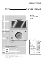
GRUNDIG Service

Vertiga UMS 5101 CDC

1 - 13

ENGLISH

9

OVERVIEW

__________________________________________________________________________________

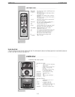
The remote control

9

Switches the stereo system into and out of stand-by mode.

SLEEP

For activating and setting the sleep timer.

DIMMER

Switches the display between three brightness levels.

X-BASS

For boosting the bass.

DSC

Selects the various sound settings.

VOCAL

Switches the VOCAL sound setting on and off.

CT

In tuner mode: switches surround sound on and off.

PTY/EON

In tuner mode: activates the search for program types; calls
up the EON (Enhanced Other Network) functions.

FM MODE

In tuner mode: switches between stereo and mono reception.

AUTO PRESET

In tuner mode: starts the automatic search programming.

REPEAT

In CD mode: repeats a track, the entire CD or all CDs.

RANDOM

In CD mode: activates the playback of tracks in random order.

DISC 1, 2, 3

In CD mode: select and start CD 1, 2 or 3.

DISPLAY

In tuner mode: for calling up various information in the display.
In CD mode: switches between CD mode and the time.

SLEEP

DIMMER

X-BASS

DSC

VOCAL

CT

PTY/EON

FM MODE

AUTO PRESET

REPEAT

RANDOM

DISC

DISC

DISC

PROGRAM

DISPLAY

VOLUME

AUX

CD

PROGRAM

+10UP

SET

DOWN

ǵ

1

2

3

UP

BAND

TUNER

6

10

OVERVIEW

__________________________________________________________________________________

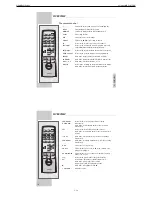
PROGRAM

In tuner mode: for step-by-step selection of stored

UP/DOWN

radio stations.
In CD mode: for selecting CD tracks in order to create a
track memory.

SET

In tuner mode: for manually storing radio stations.
In CD mode: for storing CD tracks in order to create a track
memory.

+10 UP

In CD mode: selects tracks in steps of ten when creating a
track memory.

PROGRAM

In CD mode: for creating a track memory; calls up an existing
track memory.

AUX

Selects the »

AUX

« input source.

CD 

ı

II

Selects the input source »

CD

«; in CD mode: starts CD play-

back, pauses playback.

BAND/TUNER

Selects the input source »

TUNER

« and selects the frequency

bands »

FM

« or »

MW

«.

5a

In tuner mode: press briefly to change the frequency 

s6

in small steps. Hold down to start the station search.
In CD mode: press briefly to select a track.
Hold down to search for a particular passage.

In CD mode: ends playback of the CD.

+ VOLUME –

Adjust the volume.

SLEEP

DIMMER

X-BASS

DSC

VOCAL

CT

PTY/EON

FM MODE

AUTO PRESET

REPEAT

RANDOM

DISC

DISC

DISC

PROGRAM

DISPLAY

VOLUME

AUX

CD

PROGRAM

+10UP

SET

DOWN

ǵ

1

2

3

UP

BAND

TUNER

6

Summary of Contents for GLL0452

Page 1: ...8 0180 52318 42 0180 52318 43 0180 52318 44 0180 52318 45 0180 52318 51 0180 52318 99 Mo Fr 8 00 18 00 Uhr Telefon 0180 52318 40 0180 52318 50 Fax Technik Ersatzteil Verkauf Mo Fr 8 00 19 00 Uhr Kunde...

Page 2: ...Unit 3 3 Main Circuit Diagram Main Board 3 4 Control PCB 3 7 Display PCB 3 8 Volume Control PCB 3 9 Amplifier PCB 3 10 Tuner 3 12 CD Part 3 14 Exploded View and Spare Parts List 4 1 4 3 Inhaltsverzei...

Page 3: ...es Netzstecker ziehen Leitungsverlegung Bevor Sie die Leitungen und insbesondere die Masseleitungen l sen muss die Leitungsverlegung zu den einzelnen Baugruppen beachtet werden Nach erfolgter Reparatu...

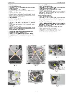
Page 4: ...1 Cabinet Undo 9 screws A Fig 1 and 2 screws B Fig 2 Pull off the back panel C Undo 2 screws D Fig 2 Take off the side covers 2 Oberteil E abnehmen R ckwand und Seitenteile abnehmen Pkt 1 2 Rastnasen...

Page 5: ...NF Platte P ausbauen Fig 10 Boden Platte ausbauen Pkt 3 2 Schrauben R Fig 2 herausdrehen NF Platte mit K hlk rper herausnehmen Stecker nach Bedarf abziehen 4 Removing Main Board Remove top cover para...

Page 6: ...en Pkt 1 Schieber A Fig 16 bis zum Anschlag nach vorne schieben Schieber B bis zur Stellung wie in Fig 17 nach vorne schieben Die CD Schublade kann jetzt mit der Hand herausgeschoben wer den 9 Removin...

Page 7: ...BASS TIMER DISPLAY TIMER SET ALL EJECT VOLUME AUX TUNER BAND CD 10 AUF EINEN BLICK______________________________________________________________________ PROGRAM Im Tuner Betrieb zum schrittweisen Anw...

Page 8: ...MER SET ALL EJECT VOLUME AUX TUNER BAND CD OVERVIEW__________________________________________________________________________________ 6 The display on the stereo system J Show the level of the input s...

Page 9: ...______________ The back of the stereo system FM EXT Antenna socket for the rooftop antenna or the supplied wire aerial AM EXT Aerial terminals for the wire antenna supplied OPTICAL Digital output for...

Page 10: ...Y EON FM MODE AUTO PRESET REPEAT RANDOM DISC DISC DISC PROGRAM DISPLAY VOLUME AUX CD PROGRAM 10UP SET DOWN 1 2 3 UP BAND TUNER 6 10 OVERVIEW____________________________________________________________...

Page 11: ...Couple Signal Generator via Loop Antennas Ue 50dB V fmod 1kHz Oscilloscope to Loudspreaker Output FM 98 1MHz Signal Generator to FM Aerial Input Ue 20dB V fmod 1kHz Deviation 75kHz Distortion Meter t...

Page 12: ...DRIVER M66004 ELE VOLUME SOUND CONTROL UPC1857 DBBS BA4558 POWER AMP LA4728 MAIN POWER TRANS RECTIFIER KEY BOARD CD LOADER DRIVER LB1641 REG 5V REG 9V TU AMP REG 5V CD SP MOTOR Microcomputer MN101C15...

Page 13: ...0 J205 CN402 CN404 CN406 CN407 P9 P11 P7 P5 P8 P6 P15 Q400 CN408 CON4 CN503 CN512 CN454 CN452 CN453 CN450 CN451 CN455 P1 GND CN602 CN601 P2 P1 GND Front TRANSFORMER MAIN TRANSFOMER P60 CN605 CN604 CN6...

Page 14: ...4W 10K C3330 F 5 6 F 1 T05591B JUMPER SDT S 112LMRR OEG 0038A HJC 027 103M250V 4001 F 1 F 5 6 4 7v 4 7u 50v 22u 50v 22u 50v 39v 223 223 223 223 6A2G 220u 50v 330 223 100u 50v 4001 4001 B1375 LINE FIL...

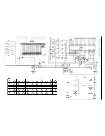
Page 15: ...21 22 23 24 25 26 27 28 FM 2 31 2 69 0 0 0 0 01 5 18 5 18 5 21 0 01 5 2 0 5 16 0 06 PIN 29 30 31 32 33 34 35 36 37 38 39 40 41 42 FM 0 0 5 16 0 0 01 0 0 04 0 0 0 0 0 5 2 4 14 PIN 43 44 45 46 47 48 49...

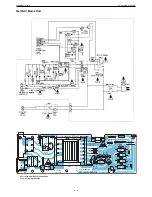
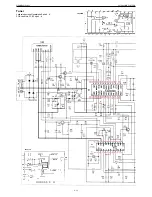
Page 16: ...GRUNDIG Service Vertiga UMS 5101 CDC 3 5 Hauptschaltplan Main Circuit Diagram...

Page 17: ...4148 330 100uF 25v 104M 10uH 10uF 4v3 47k 33k 150p C3330 4148 2 2uF 223 10k C3330 150p 220 104M 104M 100K 10k 104M 104M 4148 100uF 220 220 220 220 BA3835s 150p 150p 150p 150p 150p 150p 8MHz 15p 15p 5...

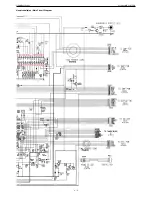
Page 18: ...T UP DOWN POWER ON X BASS 5k6 3k9 2k7 2k2 1K5 1K2 2k2 47k 18k 22k 2k4 1k5 1k2 2k2 1k2 2k2 NSX 2500 CONTROL BOARD R524 R533 R529 R528 R523 R535 R536 R541 R534 R537 R538 R539 R540 R527 R526 R525 CN504 S...

Page 19: ...5 27 8 27 8 27 9 27 6 28 1 PIN 15 16 17 18 19 20 21 22 23 24 4 6 2 5 5 5 5 1 2 3 2 3 0 27 4 15 5 PIN 29 30 31 32 33 34 35 36 37 38 17 7 27 4 25 5 29 6 21 5 13 5 15 5 27 6 25 4 23 5 PIN 43 44 45 46 47...

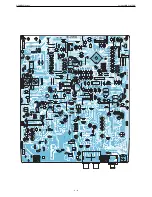
Page 20: ...1k R523 J2 C514 C513 J18 J60 J59 J61 L501 L502 R522 R520 R521 R544 R506 R507 R508 R519 R514 R513 R510 R509 R512 R511 R500 R501 R502 R503 R504 R505 J65 C505 C506 C508 CON4 CON3 SE501 S501 S504 S506 S50...

Page 21: ...GRUNDIG Service Vertiga UMS 5101 CDC 3 10 Verst rkerplatte Amplifier PCB BA4558N LA4725A...

Page 22: ...uH 2 2 2 2 104M 104M 2 2 2 2 104M 104M 1u 33u 220P 4u7 100u25v 10u 10u 15k 22K 22K 15k 3330 10u 3330 10u 220P LA4728 GND P1 C551 CN455 C491 J303 L451 C490 J302 J301 R584 J200 J220 J201 J119 CN452 C424...

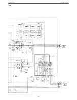
Page 23: ...GRUNDIG Service Vertiga UMS 5101 CDC 3 12 Tuner Leiterplatte siehe Hauptplatte Seite 3 6 PCB see Main PCB Page 3 6 LC72136 TA2099N...

Page 24: ...GRUNDIG Service Vertiga UMS 5101 CDC 3 13 SAA6588T Tuner...

Page 25: ...GRUNDIG Service Vertiga UMS 5101 CDC 3 14 CD Teil CD Part...

Page 26: ...GRUNDIG Service Vertiga UMS 5101 CDC 3 15 to MAIN PCB CN 409 S P 3 5 to AMPLIFIER PCB CN 451 S P 3 10 to MAIN PCB CN 407 S P 3 5 CD Teil CD Part...
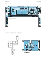
Page 27: ...GRUNDIG Service Vertiga UMS 5101 CDC 3 16 Ansicht von der L tseite View on solder side CD Teil CD Part...
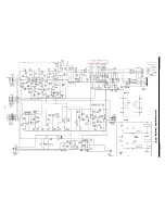
Page 28: ...GRUNDIG Service Vertiga UMS 5101 CDC 3 17 Ansicht von der Best ckungsseite View on component side CD Teil CD Part...

Page 29: ...GRUNDIG Service Vertiga UMS 5101 CDC 4 1 Explosionszeichnung und Ersatzteilliste Exploded View and Spare Parts List 38 9 28 1 12 11 40 14 39 13 2 25 15 10 26 16 VERTIGA UMS 5101 1...

Page 30: ...0324400 LED DIODE SLC 22VR 3F ROT D 00501 759550603000 LED DIODE ZGA2 SB14E2 560 D 00502 759550603000 LED DIODE ZGA2 SB14E2 560 D 00503 830921504500 DIODE 1N4148 AV619 GA D 00506 830921504500 DIODE 1N...

Page 31: ...AKTSCHALTER RS 014RB S 00516 759550489200 TAKTSCHALTER RS 014RB S 00517 759550489200 TAKTSCHALTER RS 014RB S 00518 759550489200 TAKTSCHALTER RS 014RB S 00519 759550489200 TAKTSCHALTER RS 014RB S 00520...

Reviews: