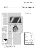
GRUNDIG Service
Vertiga UMS 5101 CDC
1 - 2
Es gelten die Vorschriften und Sicherheitshin-
weise gemäß dem Service Manual "Sicherheit",
Materialnummer 720108000000, sowie zusätz-
lich die eventuell abweichenden, landes-
spezifischen Vorschriften!
The regulations and safety instructions shall be
valid as provided by the "Safety" Service Manual,
part number 720108000000, as well as the re-
spective national deviations!
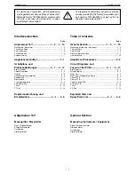
Table of Contents
Page
General Section ............................ 1 - 2 … 1 - 13
Measuring Instruments / Equipment .......................................... 1 - 2
Technical Data ........................................................................... 1 - 3
Service Hints .............................................................................. 1 - 3
Disassembly Instructions ........................................................... 1 - 4
Operating Hints ........................................................................ 1 - 10
Adjustment Procedures .............................. 2 - 2
Circuit Diagrams and
Layout of the PCBs ...................... 3 - 1 … 3 - 17
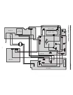
Block Diagram ............................................................................ 3 - 1
Wiring Diagram .......................................................................... 3 - 2
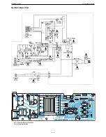
Mains Unit .................................................................................. 3 - 3
Main Circuit Diagram/Main Board .............................................. 3 - 4
Control PCB ............................................................................... 3 - 7
Display PCB ............................................................................... 3 - 8
Volume Control PCB .................................................................. 3 - 9
Amplifier PCB ........................................................................... 3 - 10
Tuner ........................................................................................ 3 - 12
CD Part .................................................................................... 3 - 14
Exploded View and
Spare Parts List .............................. 4 - 1 … 4 - 3
Inhaltsverzeichnis
Seite
Allgemeiner Teil ........................... 1 - 2 … 1 - 10
Messgeräte / Messmittel ............................................................ 1 - 2
Technische Daten ...................................................................... 1 - 3
Servicehinweise ......................................................................... 1 - 3
Ausbauhinweise ......................................................................... 1 - 4
Bedienhinweise .......................................................................... 1 - 7
Abgleichvorschriften .................................. 2 - 1
Schaltpläne und
Platinenabbildungen .................... 3 - 1 … 3 - 17
Blockschaltplan .......................................................................... 3 - 1
Verdrahtungsplan ....................................................................... 3 - 2
Netzteil ....................................................................................... 3 - 3
Hauptschaltplan/Hauptplatte ...................................................... 3 - 4
Bedienplatte ............................................................................... 3 - 7
Displayplatte .............................................................................. 3 - 8
Lautstärkereglerplatte ................................................................ 3 - 9
Verstärkerplatte ........................................................................ 3 - 10
Tuner ........................................................................................ 3 - 12
CD-Teil ..................................................................................... 3 - 14
Explosionszeichnung und
Ersatzteilliste .................................. 4 - 1 … 4 - 3
Allgemeiner Teil
Messgeräte / Messmittel
Mess- / Wobbel-Sender
Klirrfaktor-Messgerät
Oszilloskop
Digital-Voltmeter
General Section
Measuring Instruments / Equipment
Signal / Sweep Generator
Distortion Meter
Oscilloscope
Digital Voltmeter
Summary of Contents for GLL0452
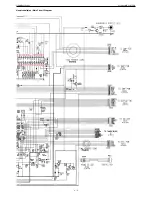
Page 16: ...GRUNDIG Service Vertiga UMS 5101 CDC 3 5 Hauptschaltplan Main Circuit Diagram...
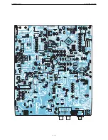
Page 21: ...GRUNDIG Service Vertiga UMS 5101 CDC 3 10 Verst rkerplatte Amplifier PCB BA4558N LA4725A...
Page 24: ...GRUNDIG Service Vertiga UMS 5101 CDC 3 13 SAA6588T Tuner...
Page 25: ...GRUNDIG Service Vertiga UMS 5101 CDC 3 14 CD Teil CD Part...

