GRUNDIG Service
Vertiga UMS 5101 CDC
1 - 6
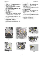
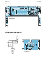
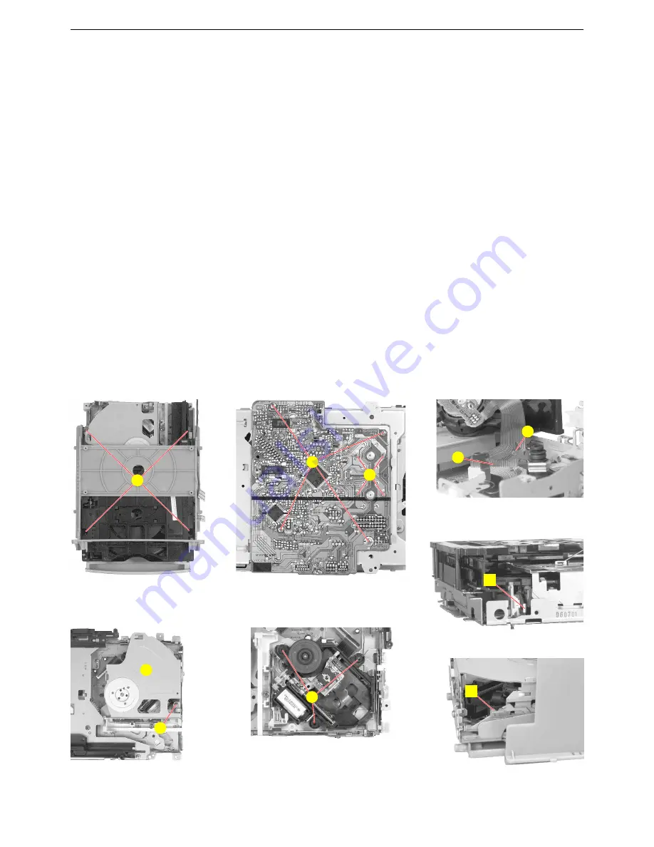
Fig. 11
Fig. 12
Fig. 13
S
T
U
V
W
Fig. 14
Fig. 15
X
Y
Z
Fig. 17
Fig. 16
A
B
9. CD-Platte ausbauen
- Front-Platte ausbauen (Pkt. 6).
- 4 Schrauben
S
(Fig. 11) herausdrehen und Laufwerk aus dem
Rahmen herausziehen.
- Die Motoranschlüsse
T
(Fig. 12) ablöten.
- 4 Schrauben
U
(Fig. 12) herausdrehen und die CD-Platte heraus-
nehmen.
- Flexprint
V
(Fig. 13) abziehen.
Achtung: Vor dem Abziehen der Flexprintleitung die Schutz-
lötstelle
W
(Fig. 13) zulöten! Die Laserdiode kann sonst durch
statische Aufladung zerstört werden.
10. Pick-Up ausbauen
- Front-Platte ausbauen (Pkt. 6).
- 4 Schrauben
S
(Fig. 11) herausdrehen und Laufwerk aus dem
Rahmen herausziehen.
- Schraube
X
herausdrehen und Abdeckung
Y
abnehmen
(Fig. 14).
- Pick-Up aus den Gummipuffern
Z
(Fig. 15) aushängen und her-
ausnehmen.
- Flexprint
V
(Fig. 13) abziehen.
Achtung: Vor dem Abziehen der Flexprintleitung die Schutz-
lötstelle
W
(Fig. 13) zulöten! Die Laserdiode kann sonst durch
statische Aufladung zerstört werden.
11. CD-Schublade bei defekter Laufwerksmechanik öffnen
- Rückwand und Seitenteile abnehmen (Pkt 1).
- Schieber
A
(Fig. 16) bis zum Anschlag nach vorne schieben.
- Schieber
B
bis zur Stellung wie in Fig. 17 nach vorne schieben.
- Die CD-Schublade kann jetzt mit der Hand herausgeschoben wer-
den.
9. Removing the CD Board
- Remove the Front Board (para 6).
- Undo 4 screws
S
(Fig. 11) and pull out the drive from the frame.
- Unsolder the motor connections
T
(Fig. 12).
- Undo 4 screws
U
(Fig. 12) and take out the CD board.
- Unplug the flexprint
V
(Fig. 13).
Caution: Before unplugging the flexprint close the protective
solder joint
W
(Fig. 13)! The laser diode may otherwise be
destroyed by static electricity.
10. Removing the Pick-Up Unit
- Remove the Front Board (para 6).
- Undo 4 screws
S
(Fig. 11) and pull out the drive from the frame.
- Undo screw
X
and remove the cover
Y
(Fig. 14).
- Unhinge the pick-Up from the rubber shock-mounts
Z
(Fig. 15) and
take it out.
- Unplug the flexprint
V
(Fig. 13).
Caution: Before unplugging the flexprint close the protective
solder joint
W
(Fig. 13)! The laser diode may otherwise be
destroyed by static electricity.
11. Opening the CD Tray with Defective Drive Mechanism
- Remove back panel and side covers (para 1).
- Pull slider
A
(Fig. 16) forward until the stop.
- Pull slider
B
forward until the position shown in Fig. 17.
- The CD tray can now be pushed out by hand.
Summary of Contents for GLL0452
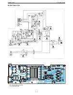
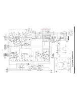
Page 16: ...GRUNDIG Service Vertiga UMS 5101 CDC 3 5 Hauptschaltplan Main Circuit Diagram...
Page 21: ...GRUNDIG Service Vertiga UMS 5101 CDC 3 10 Verst rkerplatte Amplifier PCB BA4558N LA4725A...
Page 24: ...GRUNDIG Service Vertiga UMS 5101 CDC 3 13 SAA6588T Tuner...
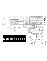
Page 25: ...GRUNDIG Service Vertiga UMS 5101 CDC 3 14 CD Teil CD Part...

