GRUNDIG Service
VERTIGA UMS 4600 DEC
1 - 3
Technische Daten
System
Spannungsversorgung:
Betriebsspannung ................................................................... 230V~
Netzfrequenz ........................................................................ 50/60Hz
Max. Leistungsaufnahme ........................................................... 28W
Leistungsaufnahme in Stand-by ................................................
≤
5W
Verstärkerteil
Ausgangsleistung:
Sinusleistung .......................................................................... 2 x 5W
Musikleistung ......................................................................... 2 x 8W
Empfangsteil
Empfangsbereich:
FM .......................................................................... 87,5 ...108,0MHz
MW ........................................................................... 522 ... 1620kHz
CD Teil
Frequenzgang .......................................................... 100Hz ... 15kHz
Geräuschspannungsabstand (bewertet) .................................
≥
60dB
MP3-Features
Alben und Files ................... Max. 200 Alben, max. 500 Files pro CD
File System/File Management ............ ISO 9660 Level 1 kompatibel
Abmessungen
Abmessungen Gerät B x H x T .......................... 170 x 172 x 250mm
Abmessungen Lautsprecher B x H x T .............. 128 x 255 x 148mm
Gewicht
Gewicht Gerät ........................................................................... 2,4kg
Gewicht pro Lautsprecher ........................................................ 0,8 kg
Technical Data
System
Power supply:
Operating voltage ................................................................... 230V~
Mains frequency ................................................................... 50/60Hz
Max. power consumption .......................................................... 28W
Power consumption in stand-by .................................................
≤
5W
Amplifier unit
Output:
Sine wave power .................................................................... 2 x 5W
Music signal power ................................................................ 2 x 8W
Receiver unit
Reception range:
FM .......................................................................... 87.5 ...108.0MHz
MW ........................................................................... 522 ... 1620kHz
CD unit
Frequency response ................................................ 100Hz ... 15kHz
Noise-voltage ratio (wtd.) ........................................................
≥
60dB
MP3 features
Albums and files: ............... Max. 200 albums, max. 500 files per CD
File system/file management .............. ISO 9660 Level 1 compatible
Dimensions
Device dimensions W x H x D ........................... 170 x 172 x 250 mm
Loudspeaker dimensions W x H x D .................. 128 x 255 x 148mm
Weight
Device weight ............................................................................ 2.4kg
Weight per loudspeaker ............................................................ 0.8kg
Servicehinweise
Achtung: ESD-Vorschriften beachten
Vor Öffnen des Gehäuses Netzstecker ziehen.
CD-Laufwerk
Bei Ausbau der Lasereinheit oder der Servo-Leiterplatte muß vor
Abziehen der Steckverbindung eine Schutzlötstelle auf der Leiter-
platte der Lasereinheit angebracht werden, um eine Zerstörung der
Laserdioden durch statische Aufladung zu vermeiden.
Beim Einbau einer neuen Lasereinheit (CD-Laufwerk) muß nach
Einstecken der Steckverbinder die werkseitig angebrachte
Schutzlötstelle entfernt werden!
Service Hints
Attention: Observe the ESD safety regulations
Disconnect the mains plug before opening the set.
CD Mechanism
When removing the Laser pick-up or the Servo PCB, the Laser pick-
up PCB must be provided with a protective soldered joint before
unplugging the connectors to avoid damage to the Laser diodes by
static charges.
When inserting the new Laser pick-up (CD drive mechanism) the
soldered joint fitted at the factory must be removed after the
connectors are plugged in.
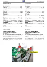
Schutzlötstelle
Protective soldered joint
Summary of Contents for GLR1200
Page 5: ...GRUNDIG Service VERTIGA UMS 4600 DEC 1 5...
Page 6: ...GRUNDIG Service VERTIGA UMS 4600 DEC 1 6...
Page 7: ...GRUNDIG Service VERTIGA UMS 4600 DEC 1 7...
Page 9: ...GRUNDIG Service VERTIGA UMS 4600 DEC 1 9...
Page 10: ...GRUNDIG Service VERTIGA UMS 4600 DEC 1 10...
Page 11: ...GRUNDIG Service VERTIGA UMS 4600 DEC 1 11...
Page 16: ...GRUNDIG Service VERTIGA UMS 4600 DEC 3 Netzteil Power Supply p 3 4...
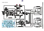
Page 17: ...GRUNDIG Service VERTIGA UMS 4600 DEC 3 Verst rker Amplifier p 3 6 p 3 6 p 3 3 p 3 6 p 3 6...
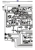
Page 18: ...GRUNDIG Service VERTIGA UMS 4600 DEC 3 Hauptplatte Main PCB to CN792 p 3 9 to W403 p 3 8...
Page 20: ...GRUNDIG Service VERTIGA UMS 4600 DEC 3 Hauptplatte Main PCB...
Page 23: ...GRUNDIG Service VERTIGA UMS 4600 DEC 3 10 CD Teil CD Section...
Page 24: ...GRUNDIG Service VERTIGA UMS 4600 DEC 3 11 USB Teil USB Section to W402 p 3 9...
Page 25: ...GRUNDIG Service VERTIGA UMS 4600 DEC 3 12 USB Teil USB Section...
Page 27: ...GRUNDIG Service VERTIGA UMS 4600 DEC 3 14 Display Platte Bedienteil Display Board Keyboard...


