GRUNDIG Service
OVATION CDS 7000 SPCD
2 - 2
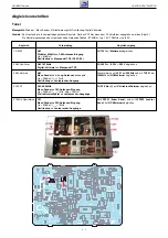
Adjustment Procedure
Tuner
Test equipment: Sweep / Signal Generator, Distortion Meter, Oscilloscope, Digital Voltmeter
Note: The frontend is a completely preadjusted module. Only the IF filter must be adjusted to the IF amplifier (Adjustment 4).
The values of the tuning voltages are as follows: 87.5MHz = typ. 1.6V; 108MHz = typ. 8.0V.
Adjustment
Preparation
Adjustment Procedure
1. AM IF
2. AM Oscillator
3. AM Band Pass
4. FM IF
5. 19kHz Filter
AM;
Sweep Generator 450kHz to AM Aerial Input;
Ue > 60dB
µ
V;
Oscilloscope to Testpoint TP5, IC502-(19).
AM, 1620kHz;
Digital Voltmeter to Testpoint TP3.
AM;
Couple Signal Generator via Loop Antennas;
Ue > 50dB
µ
V; f
mod
= 1kHz;
Oscilloscope to Loudspeaker Output.
FM, 98.0MHz
Signal Generator to FM Aerial Input;
Ue = 20dB
µ
V; f
mod
= 1kHz; Deviation = 75kHz;
Distortion Meter to Loudspeaker Outputs.
FM;
Signal Generator to FM Aerial Input;
Ue = 50dB
µ
V; f
mod
= 19kHz;
Oscilloscope to Loudspeaker Outputs.
Adjust with T501 for Maximum.
Adjust with L502 for 8.25V
±
0.25V.
Adjust alternating with L501 at 558kHz and with TC501 at
1440kHz for AF Maximum.
Adjust with IF Filter
A
for Distortion Minimum.
Adjust with LPF501 (left channel) and with LPF502 (right
channel) for AF Minimum.
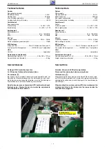
TP3
TP5
Summary of Contents for GLR2100
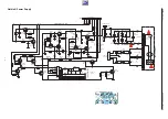
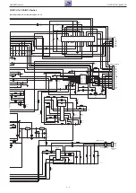
Page 5: ...GRUNDIG Service OVATION CDS 7000 SPCD 1 5...
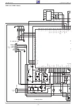
Page 6: ...GRUNDIG Service OVATION CDS 7000 SPCD 1 6...
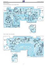
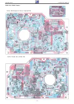
Page 7: ...GRUNDIG Service OVATION CDS 7000 SPCD 1 7...
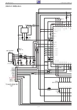
Page 9: ...GRUNDIG Service OVATION CDS 7000 SPCD 1 9...
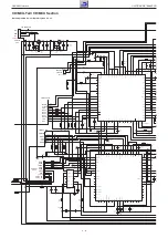
Page 10: ...GRUNDIG Service OVATION CDS 7000 SPCD 1 10...
Page 11: ...GRUNDIG Service OVATION CDS 7000 SPCD 1 11...
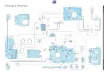
Page 16: ...GRUNDIG Service OVATION CDS 7000 SPCD 3 Verdrahtungsplan Wiring Diagram...


