GV 27 EURO, GV 7… EURO
Partie générale / General Section
GRUNDIG Service
1 - 13
Formation pour le remontage:
– Placer le C.I. principal avec la mécanique dans le cadre du boîtier (le
saisir que par le côté du logement de cassette) de façon à engager
l'embase secteur et les embases EURO-AV dans les guidages
correspondants. Tous les 10 crochets doivent être verrouillés.
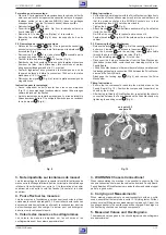
– Revisser les 4 vis
U
(Fig. 6).
– Poser l'étrier
G
comme indiqué Fig. 3 sur le cadre du boîtier et le
fixer à l'aide des 2 vis
F
.
– Remettre le C.I. embases Line (Option) et le raccorder.
– Remettre les câbles
K
(Fig. 6) dans les supports du dos de
l'appareil.
2.2 Démontage de la platine mécanique
– Défaire les verrous
R
et
S
(Fig. 5) du logement de cassette et
pousser celui-ci suffisamment vers l'intérieur pour rendre les vis
U
accessibles (Fig. 6).
– Dévisser les 4 vis
U
et la vis de masse
T
(accessible par le
perçage du dos de l'appareil) (Fig. 6).
– Courber la tôle de protection
W
vers l'arrière (Fig. 6).
– Débrancher les 5 connecteurs de liaison entre la platine mécanique
(tambour de têtes, tête d'effacement, tête combinée et moteur
d'engagement/dégagement) et le C.I. principal.
– Soulever légèrement avec précaution la mécanique au dos de
l'appareil de façon à défaire le connecteur 1946 entre la platine
mécanique et le C.I. principal.
– Décrocher les ergots
Y
(Fig. 5) et retirer la platine mécanique du
magnétoscope.
Instruction pour le remontage:
– Aucun composant ne doit s'insérer dans les zones marquées
(Fig. 10). Les composants (condensateurs) doivent être arrangés
comme indiqué par les flèches.
– Après le remontage de la platine mécanique il y a lieu de rétablir la
liaison de masse entre le C.I. principal et la mécanique en revissant
la vis de masse
T
(Fig. 6).
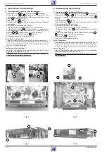
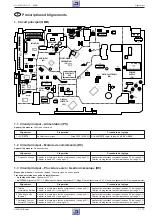
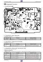
Fig. 9
Fig. 10
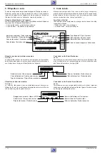
3. Note importante sur les liaisons de masse!
Lors du remontage de l'appareil, respecter et contrôler les liaisons de
masse entre le blindage inférieur et le circuit principal, entre le blindage
inférieur et le boitier supérieur, entre le C.I. alimentation et le boitier
supérieur ainsi qu'entre le volet de facade (Variante) et le boitier
supérieur.
4. Pour effectuer les mesures
Lors de mesures à l'oscilloscope sur des semi-conducteurs utiliser
uniquement une sonde de rapport 10:1. En outre il est à noter qu'en cas
de mesures antérieures faites en alternatif, le condensateur d'entrée
de l'oscilloscope peut être chargé. Ce dernier peut se décharger et
détruire ainsi le composant mesuré.
5. Valeurs des mesures et oscillogrammes
Les valeurs de mesures indiquées sur les schémas et les
oscillogrammes sont des valeurs approximatives!
3. WARNING: Chassis Connections!
When reassembling the machine it is essential to observe that the
chassis connections between the cabinet bottom and Family Board,
Family Board and Drive Mechanism, cabinet bottom and cabinet upper
part are in good order.
4. Carrying out Measurements
When making measurements on semi-conductors with an oscillo-
scope, ensure that the test probe is set to 10:1 dividing factor. Further,
please note that if the previous measurement is made on AC input, the
coupling capacitor in the oscilloscope will be charged. Discharge via
the item being checked can damage components.
5. Measured Values and Oscillograms
The measured values given in the circuit diagrams and oscillograms
are approximates!
Fitting Instructions:
– Put the Family Board together with the Drive Mechanism (take it only
by the side of the cassette compartment) into the cabinet frame so
that the mains socket and the EURO-AV sockets are in their
appropriate guides. All 10 catches must lock in.
– Tighten the 4 screws
U
(Fig. 6).
– Attach bracket
G
to the cabinet frame as shown in Fig. 3 and fasten
it with the 2 screws
F
.
- Re-fit the Line socket board (option) and re-connect it.
- Fasten the cables
K
(Fig. 6) with the holders on the rear side of the
cabinet.
2.2 Removing the Drive Mechanism
– Release the locks
R
and
S
(Fig. 5) of the cassette compartment
and move it inwards to gain access to the screws
U
(Fig. 6).
– Undo the 4 screws
U
and the earthing screw
T
(accessible
through the hole of the cabinet rear side) (Fig. 6).
– Push the shielding plate
W
(Fig. 6) to the rear.
– Disconnect the 5 plug-in connections from the Drive Mechanism
(headwheel, erase head, combi-head and threading motor) to the
Family Board.
– Lift the Drive Mechanism on the rear side carefully by a small amount
to disengage the plug-in connection 1946 between the Drive Mecha-
nism and the Family Board.
– Disengage the locking lugs
Y
(Fig. 5) and remove the Drive
Mechanism.
Fitting Instructions:
– Ensure that no components reach into the marked areas on the
Family Board (Fig. 10). Position the components (capacitors) as
shown by the arrows.
– After having re-fitted the Drive Mechanism, re-establish the chassis
connection between the Family Board and the Drive Mechanism by
tightening the earthing screw
T
(Fig. 6).
voir point 2.2
see para 2.2


