GV 27 EURO, GV 7… EURO
Service Test Programme & Special Functions
GRUNDIG Service
2 - 5
k
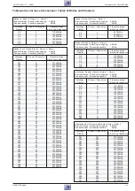
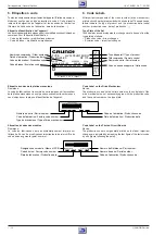
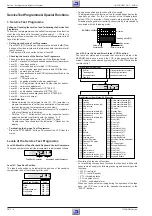
Level 03: Man. Tracking, Tape Deck Sensors and VCR Function
– Manual tracking
The tracking position in the service test programme is set to mid-
position. By pressing the "+" or "–" button it is possible to change the
tracking position to the required position for tape transport adjust-
ment (see chap. 5 – Tape Deck).
– Tape deck sensors
For checking the tape deck sensors (Init switch, threading tacho,
tape start, tape end, record lock, winding tacho left / right) the
operating positions are indicated on the display by means of one
digit. The indicated value changes with each operation of the
sensors.
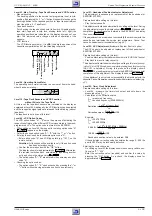
– VCR function
The VCR function symbols (
■
●
r
e
) indicate the position of the
cassette compartment and of the threading roller units.
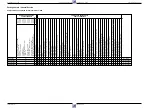
VCR function
Threading tacho
(FTA)
Init switch
(INIT)
Record prodection
(RECP)
Beginning of tape
End of Tape
Left reel tacho
(Option)
Right reel tacho
Level 04: Operating Hours Meter
The operating hours meter indicates the number of hours the head-
wheel has been rotating.
Level 10: Tape Deck Sensors and VCR Function
without Drive to the Tape Deck
At this level, the tape deck sensors are indicated on the display as
explained at Level 03. Additionally, the VCR functions can be selected
and the respective signal paths are released for fault finding (without
tape deck).
The tape deck is not driven at this level.
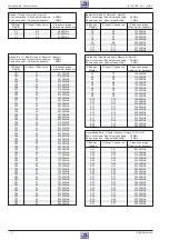
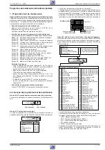
Level 40: VCR Option Codes
The VCR option codes "A"…"E" serve the purpose of activating the
respective software of the different VCR versions stored in the mask-
programmed
µ
C's. The option code is stored in the EEPROM.
– When calling up Level 40 the request for entering option code "A"
(
) appears on the display.
– Select the desired option code "A"…"E" with the "–" or "+" button.
– Entering the option code, for example option code "A":
– Enter option code "A", see VCR type plate (e.g. "191"), on the
remote control.
Attention: All functions will be available only if the option code
has been entered correctly.
– Confirm the entered code with the "OK" button.
The display shows for approximately 3s
. Afterwards,
the recorder switches back automatically requesting another
entry and shows the stored value
.
– The option codes "B"…"E" are entered in the same way as option
code "A".
– Checking the option codes:
– The option codes "A"…"E" can be checked by pressing the "–" or
"+" button without having entered an option code previously.
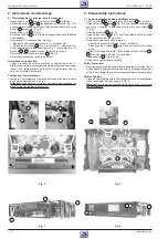
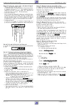
Level 51: Headwheel Position Indicator Adjustment
This adjustment is necessary on replacement of the headwheel or
EEPROM (IC7890).
Preparation before calling up this level:
– Play the test cassette.
This adjustment is started automatically on calling up the level. During
the adjustment process the display shows
. On successful
completion the resulting value is stored in the EEPROM. The display
then shows
.
If the adjustment is not carried out successfully the machine ejects the
cassette and terminates the service test programme. Cause: Test
cassette, headwheel or technical defect (e.g.
µ
C)
Level 52: ACC Adjustment (Automatic Contour Control, option)
The ACC needs to be adjusted on replacement of the headwheel or
EEPROM (IC7890)
Preparation before calling up this level:
– Feed in a black raster test pattern without burst to EURO-AV1 socket
– Play back the record / play cassette.
This adjustment is started automatically on calling up this level
(record-
ing for 10s in SP/LP mode each and while playing back this recording
the VCR is adjusted). During this process the display shows
.The resulting value is stored in the EEPROM on successful
completion of this adjustment. The display then shows
.
If the adjustment is not carried out successfully the machine ejects the
cassette. Cause: Preparation, cassette, headwheel or technical defect (e.g.
µ
C).
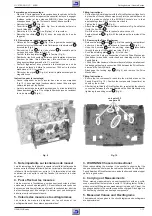
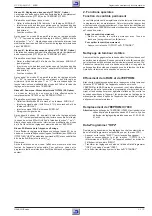
Level 53: Timer Clock Adjustment
Preparation before calling up this level:
– Level 99 - measure the timer clock output and note down the
measured value (f
mess
).
– Calculation of the correction value:
f
mess
= measured frequency
f
soll
= desired frequency (2048.0000Hz)
1 x 10
6
x (f
mess
– f
soll
)
f
soll
Deviation =
Deviation
0.763
Correction value =
+128
Example:
f
mess
= 2047.9700Hz
f
soll
= 2048.0000Hz
1 x 10
6
x (2047.97Hz – 2048Hz)
2048Hz
-14.648 =
-14.648
0.763
108.80 =
+128
Rounded correction value to be entered: 109
If the calculated correction value lies outside the range 0…255 the
quartz Q1297 may be technically defective.
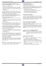
Entering the correction value
– On calling up Level 53 the display shows the currently valid correc-
tion value "0"…"255".
– Enter the correction value (rounded) and confirm the value by
pressing the "OK" button. As a check, the display shows for
approximately 3s
.

