background image

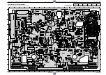
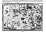
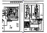
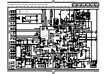
Platinenabbildungen und Schaltpläne / Layout of PCBs and Circuit Diagrams

GV 27 …, GV 47 …, GV 7…

Platinenabbildungen und Schaltpläne / Layout of PCBs and Circuit Diagrams

GV 27 …, GV 47 …, GV 7…

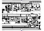
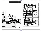
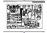
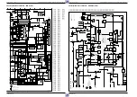
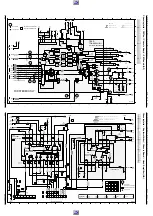
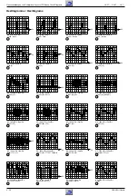
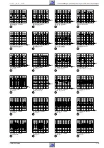
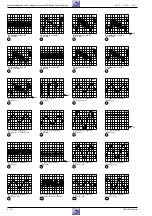
Chassisplatte / Chassis Board – Video/Chroma (VS), Standardton / Standard Sound (AL)

4 - 25

GRUNDIG Service

4 - 26

GRUNDIG Service

70

72

71

73

74

75

76

16

18

15

20

19

38

36

MONO only

1SC

2SC

3028

5k6

3k3

CTL2

CTL1

CTL2

CTL1

AINFR

AINFR

AINFL

AINFL

AOUT1L

AOUT1R

CSYNC

CSYNC

CSP

CSP

AF1

AF1

VREC

VREC

AMLP

AMLP

ISWS

ISWS

IREV

IREV

IREV

FMPV

FMPV

VOUT

VMOD

AOUT2L

AOUT2R

VBS

VBS

VFR

CKDET

CKDET

8SC2

VSB

VSB

FMRV

FMRV

2FSC

2FSC

AIN2

VFV

VFV

VFV

FFP

FFP

CROT

CROT

CSCP

CSCP

MTA

MTA

AIN1

AMLR

AMLR

AIN2R

AIN2L

AIN1R

AIN1L

SCL2

SCL2

SDA2

SDA2

SCL

SDA

8SC1

0,1V

0V

0,5V

0,3V

10,4V

0,3V

10,5V

12V

4,3V

0V

12V

12V

9,8V

0,7V

3V
0V

0V

-17V

-22V

-22V

0,7V

-22V

6,3V

7V

7V

7V

BIAS

PB-Level

1,9V

0V

0,9V

2,4V

9.5V

1,5V

2,2V

2,5V

2,5V

2,6V

5,14V

2V

0V

1,9V

0V
2V

2,9V

3,9V

3V

3,9V

3,3V

5,1V

2,1V

4,2V

2,7V

1,5V

3V

1,4V

2,1V

0V

5V

3V

1,5V

2,1V

3V

3V

1,8V

0,5V

5,1V

2,3V

0,2V

0,4V

3,1V

1,8V

0,1V

4,1V

1,8V

2,3V

2V

2,5V

2,2V

0V

3,1V

1,8V

2,4V

0,3V

2,4V

0,2V

2,7V

0V

1,6V

2,6V

4,8V

1,9V

2,6V

1,5V

4,5V

3,4V

3V

0V

1,6V

2,3V

3,3V

3,3V

3,3V

3,3V

3,6V

7V

0,2V

3,4V

3,4V

0V

0V

3,5V

3,4V

7V

3,4V

3,4V

0V

3,4V

3,4V

3,4V

1V

0V

AGC

AGC

AGC

0V

0V

3,3V

2,1V

0V

0,6V

1,8V

only for 2/X + SECAM 

for mstd 220E

for 2/X 8k2

AGC

BIAS2

BIAS1

GNDAL

IC

HEAD

AF

(Deemphasis)

(Phase-Shift)

(Buffer)

(Buffer)

(SWITCH)

(SWITCH)

not used

osd include

AF

RIGHT

LEFT

CINCH

CINCH

for stereo only

not used

not used

AGC

1

2

3

for Cinch-IN front only 

PS

CTL1

CTL2

AEH1

AEH2

APH

ARH

MEH1

MEH2

TD1

TD2

VS_S,DE,HA

OS

FV

FM

DE/DC

680E for stereo

3160 for mono

not used

not used

for 1Scart only

for 4/2 only

not used

10u for stereo

for cinchout rear only 

VS_S,VPS/PDC

LP only

not used

(DELAY-Line)

(Buffer)

(VIDEO & LIN. Audioprocessor)

(Erase-Oscillator)

(Erase-Oscillator-SWITCH)

(LIN.Audio PB SWITCH)

AF,FV

for Stereo

only

for 2scart or stereo only

0V

Pal-Current

for mstd,mstds,

secdk,secdks,secdkns;

for 2/X 22p

4

5

6

7

1

8

9

10

11

12

13

14

15

16

17

18

19

2

20

21

22

23

24

25

3

M

L

K

P

J

I

H

G

F

E

D

C

B

A

O

N

4

5

6

7

1

8

9

10

11

12

13

14

15

16

17

18

19

2

20

21

22

23

24

25

3

12VA

12SW

12SW

12SW

5VASW

5VASW

12VA

5VASW

5VASW

5VA

-28V

5VASW

5VASW

5VASW

5VASW

5VASW

12SW

BZX79-B7V5

6601

BZX79-C12

6135

5130

5605

3017

1k8

3006

12k

3046

1k

3027

27k

3021

1k

3600

22k

3002

680E

3004

680E

3003

680E

3022

1k

3025

47k

3023

220k

3033

18k

3030

2k2

3031

2k2

3050

100E

3052

100E

3528

47k

3018

470E

3048

47k

3604

22k

3656

6k8

3606

47E

3005

8k2

3045

270E

3008

470E

3615

100E

3608

12k

3015

1k

3020

220k

3610

2k2

3603

100E

1%

3014

4k7

3607

390k

3011

2k2

3035

2k2

3032

2k2

3012

2k2

1%

3055

680E

1%

3054

2k2

3009

4k7

1%

3013

1k3

3560

0E

3028

3019

5k6

3609

8k2

3605

2k2

3612

2k2

3601

10k

3000

1k

3001

1k

3010

1k

3016

8k2

3026

47k

3029

2M2

3034

15k

3519

8k2

3611

100E

3602

4k7

3047

4k7

3657

390E

3655

680E

3638

10E

3619

1E5

3620

47k

3625

33E

3624

3k3

3623

10k

3622

3M3

3024

10k

3036

470E

3626

220k

3627

56k

3u3

5604

5%

100u

5026

5%

56u

5036

5%

15u

5020

5%

47u

5004

5%

150u

5005

10u

5000

10%

10u

5001

10%

10u

5002

5%

22u

5831

10m

5601

330u

5602

25V

100n

2003

50V

220p

2026

50V

33p

2038

25V

100n

2024

50V

22p

2018

25V

100n

2013

50V

10n

2011

50V

10n

2023

50V

15p

2831

21V 

SIOV-CN0805M4CCG

470p

2137

21V 

SIOV-CN0805M4CCG

470p

2138

50V

82p

2036

50V

10n

2066

50V

27p

2064

2%

50V

220p

2037

25V 

100n

2520

25V

100n

2650

25V

100n

2647

50V

10n

2603

50V

2n2

2601

50V

1n

2605

25V

100n

2001

50V

10n

2055

2%

63V

390p

2006

50V

10n

2002

50V

10n

2004

25V

100n

2009

25V 

100n

2521

25V

100n

2016

50V

10n

2030

25V

100n

2031

50V

10n

2027

50V

10n

2028

50V

10n

2029

50V

10n

2034

50V

10n

2035

25V

100n

2033

50V

47n

2045

50V

47n

2042

50V

22n

2040

50V

39p

2007

50V

22p

2008

25V

100n

2519

25V

100n

2606

50V

22p

2607

50V

10n

2608

25V

100n

2015

25V

100n

2022

50V

1n

2621

50V

330p

2618

63V

820p

2600

50V

15n

2657

50V 39n

2656

50V

10n

2047

50V

10n

2051

50V

1n

2046

BC847B

7011

BC846B

7602

BFS19

7000

BC846B

7601

BC847B

7002

BC847B

7006

BFS19

7004

BC847B

7603

AOUT2L

AOUT2R

12VA

VFV

VBS

SCL2

SDA2

5VASW

MTA

AF1

CSP

HA

VS_S

HA

2FSC

CKDET

SDA

SCL

FMRV

VMOD

CROT

FFP

12SW

CTL1

CTL2

8SC1

FMPV

5VA

CSCP

VSB

VOUT

VREC

VFV

CSYNC

AMLP

-28V

AIN1L

AIN1R

AIN2L

AIN2R

AOUT1L

AOUT1R

AMLR

AINFL

AINFR

ISWS

8SC2

IREV

BC857B

7008

BC857B

7005

BC856B

7600

BC857B

7021

GNDAL

GNDAL

GNDAIO

GNDSUB

GNDVSIO

GNDAIO

GNDAL

GNDAL

GNDAL

GNDAL

GNDAL

GNDAL

GNDAL

GNDAL

GNDAL

GNDAL

GNDAL

GNDEO

GNDAL

GNDAL

GNDAL

GNDAL

GNDEO

GNDEO

GNDEO

GNDAL

GNDEO

GNDEO

GNDAL

3134

220E

3135

220E

MMUN2112LT1

7009

MMUN2112LT1

7001

1909

1

2

1962

1

2

9013

9154

9073

9034

1002

1

2

3

1710

1

2

3

1750

1

2

3

1711

1

2

3

4

5

6

100n

2528

25V

BC817-40

7609

50V

ECQBF

27n

2622

50V

ECQBF

47n

2620

16V

47u

2619

16V

47u

2617

7604
BC328-40

10k

3007

10k

3160

100k

3618

5603

1

2

3

4

6

LA71525M

7007

10

11

13

14

15

17

18

1

20

23

25

26

28

29

58

30

31

32

33

34

35

37

38

39

3

40

42

43

45

46

48

49

4

50

51

52

54

55

56

5

61

63

64

6

71

72

73

74

75

77

78

79

7

8

9

62

2

80

76

12

53

67

57

66

47

24

70

69

68

22

60

65

44

19

59

21

41

16

27

36

P

REC

MUTE

P

R

C-GND

AMP

EQ

R

PB-

VXO1

VREF

LP,SP

AMP

ACC

DET

APC

PB

BGA-B

CONV

MAIN

CONV

SUB

DET

APC

REC

BPF

SUB

PB

DET

AFC

BAL
TC1

NC-CTL

PAL-PULSE

CSCP_IN

IN

C-ROT

PQ1

2

COMB

P

BPF2

P

AMP

REC

TH

BPF1

LPF

AMP

P

R

C-LPF

R

R

KIL

VCO

P

P

MOD

INV

DE-EM

DECODER

DHP

N.L.

MIX

Y C

CTL

PIC

NC

AGC

PM

FM

PB-EQ

EMPH

MAIN

SERIAL

SLD

CNC

SQ

1/2

FBC

C-VCC

EMPH

N.L.

REC

EQ

P

R

CTL

MUTE

HIGH

B.D.

KIL

NPP

BPF

OUT

REC

DET

ALC

ALC

DETAIL

EMPH

R

P

DOUBLE

LIMIT

DEMOD

PQ2

R

A-VCC

A-GND

PEAKING

NTSC

LPF

R

P

P

P

R

YNR

QV/QH

SEPA

SYNC

LPF

SUB

INS

DET

AGC

VCC2

VIDEO

AMP

MAIN
EMPH

VIDEO

CLP

AGC

CLP

R

P

Y-VCC

Y-GND

LINE

AMP

OUT

ACK

DET

KIL

IN3

IN1

BGP

R,A

VREF

DET

ACC

RL

B

HD
SW

2FSC/

PB-H

BGA-A

OUT

BGA

REC

PB

R

P

REC

REG

A-GND

REC-LP,EP

PB-EP

REC

16V

10u

2652

16V

47u

2049

16V

47u

2651

16V

22u

2648

16V

10u

2602

50V

1u

2044

16V

22u

2005

6,3V

220u

2010

25V

4u7

2012

50V

0u47

2014

16V

10u

2017

16V

10u

2019

16V

10u

2021

50V

1u

2054

16V

47u

2025

16V

47u

2032

50V

1u

2039

50V

1u

2041

50V

1u

2043

16V

10u

2020

6,3V

100u

2604

50V

1u

2059

1912

9381B

1

2

1911

9381C

1

2

4,433619MHz

1000

LC89980M

7003

10

11

12

13

14

1

2

3

4

5

6

7

8

9

GENERATOR

GEN

TIMING

OUTPUT AMP

AND HOLD

SAMPLE

OUTPUT AMP

AND HOLD

CLOCK

SAMPLE

AUTO BIAS

CIRCUIT 1

DL

DL

CLOCK

CLOCK

CENTER

BIAS

CIRCUIT 2

AUTO BIAS

SHAPER

WAVE

SYNC TIP

CLAMP

CENTER

DL

PHASE

COMP

DRIVER

CLOCK

BIAS

DL

1/3

VCO

CIRCUIT

SWITCHING

CLOCK

VOLT

RD

NT

VCC

NC

CLK

GND

1961

1

2

3

4

5

6

7

39

14

60

2p7

2048

40

Chrominance

Luminance

Standard Sound

Record

Standard Sound

Playback

Chrominance

Luminance

Reference
Oscillograms ....4-38
AF....................4-29

AL ....................4-25
DC ...................4-35
DE ...................4-33

FV....................4-21
FM ...................4-24
HA ...................4-30

IO.....................4-27
OS ...................4-24
PS....................4-31

QMB ................4-15
QNIC ...............4-36
VP....................4-24

VS....................4-25
VS-S ................4-28

Summary of Contents for GV 27

Page 1: ...7000 SV C GV 7003 GV 7300 SV GV 7300 SV 5 GV 7400 HiFi GV 7400 HiFi 5 GV 7400 NIC KV 7001 VPS 5 KV 7301 VPS 5 Palermo SE 7100 SV Sevilla SE 7105 HiFi GV 27 GV 47 GV 7 Sach Nr Part No 72010 530 25 Btx...

Page 2: ...F 4 29 Head Amplifier HA 4 30 Power Supply PS 4 31 Drive Control Deck Electronic DE 4 33 Display Control DC 4 35 NICAM Decoder QNIC 4 36 Oscillograms 4 38 Drive Mechanism 5 1 5 12 Test Equipment Jigs...

Page 3: ...logic Energiesparend Low Power Standby 6W Longplay Normalplay HiFi Stereo Rotierender L schkopf Flying Erase Head 2 Kopf Head Audio 4 Kopf Head Video 2 Kopf Head Video S VHS Wiedergabe S VHS Playback...

Page 4: ...Beachten Sie bitte das Grundig Me technik Programm das Sie unter folgender Adresse erhalten Grundig Instruments Test und Me systeme GmbH W rzburger Str 150 D 90766 F rth Bay Tel 0911 703 4118 Telefax...

Page 5: ...Stop Bildsuchlauf vorw rts bei Wiedergabe Vorlauf bei Stop Netzanschlu EURO AV1 Buchse Audioausgang EURO AV2 Buchse Antennenausgang Antenneneingang 1 Switches the recorder to standby 2 For selecting p...

Page 6: ...re search on playback fast forward from stop Freeze frame on playback Starts playback function Remote control of television press and hold down TV button 1 TV Monitorfunktion 2 Er ffnet die Timer Prog...

Page 7: ...die Cassettenklappe so nach innen zu dr cken da der Hebel E in die F hrung Fig 4 der Cassettenklappe eintaucht Service Instructions 1 Removing the Cabinet Parts 1 1 Cabinet Upper Part Undo 4 screws A...

Page 8: ...ng Nicht die Cassetten Ausgabe Taste dr cken und keinen Abgleich durchf hren Fig 5 Fig 6 S R Y Y 2 Disassembly Instructions 2 1 Removing the Chassis Board with Mechanics Undo 2 screws F Fig 3 and rais...

Page 9: ...den Schaltpl nen und Oszillogrammen angegebenen Me werten handelt es sich um N herungswerte 3 WARNING Chassis Connections When reassembling the machine it is essential to observe that the chassis conn...

Page 10: ...twicklungscode Evolution code A 01 40393 5 52 0 100647 1 SHOW VIEW IS A TRADEMARK APPLIED FOR BY GEMSTAR DEVELOPMENT CORP SHOW VIEW SYSTEMS IS MANUFACTURED UNDER LICENSE FROM GEMSTAR DEVELOPMENT CORPO...

Page 11: ...iedergabe r ckw rts 237 239 Laufwerkstellung und Funktion des Init Schalters Das Diagramm zeigt die Funktion des Init Schalters in Abh ngigkeit von der Stellung des Laufwerks Daf r ist die Anzahl der...

Page 12: ...onscodes B E sind genauso durchzuf hren wie bei dem Optionscode A Kontrolle der Optionscodes Durch Bet tigen der Tasten oder ohne vorheriger Options code Eingabe ist die Kontrolle der die Optionscodes...

Page 13: ...r Takt Ausgabe F r den Uhr Takt Abgleich Ebene 53 ist in dieser Ebene die Uhr Oszillatorfrequenz ca 2048Hz an IC7201 80 HEST der Bedieneinheit DC zu messen Aufl sung mindestens 6 Stellen und notieren...

Page 14: ...partment and of the threading roller units Tape Deck Positions Code Eject 005 009 Index 189 191 Stop threaded out 196 204 Play position 209 217 Play reverse 237 239 Tape deck position and function of...

Page 15: ...option codes B E are entered in the same way as option code A Checking the option codes The option codes A E can be checked by pressing the or button without having entered an option code previously...

Page 16: ...Output For adjusting the timer clock Level 53 the timer oscillator frequency approx 2048Hz must be measured at this level on IC7201 80 HEST of the keyboard control unit DC resolution 6 digits at least...

Page 17: ...20 20 2 2 21 21 1 1 1 1 8 5 1 1 1 18 10 1 9 8 5 1 1 4 6 10 1 11 12 13 14 15 16 17 18 1 7 1 1 LC74781 TDA4722 7890 24C08 7110 WTL 7465 7800 1 4 6 5 1 16 32 17 12 24 14 1 8 7 5208 ANTI CLOCHE CLOCHE 51...

Page 18: ...ttigung Verh ltnisBurst Chroma 1 2 2 an der AV1 Buchse einspeisen und aufnehmen Oszilloskop R3159 Schleifer SECAM L Rotfl chentestbild mit 75 S ttigung Verh ltnis Burst Chroma 1 2 2 an der AV1 Buchse...

Page 19: ...ervice Test Programme see page 2 4 Call up Level 51 see page 2 4 Call up the Service Test Programme see page 2 4 Call up Level 40 see page 2 4 Call up the Service Test Programme see page 2 4 Call up L...

Page 20: ...m L5001 and reassemble the drive mechanism Remove the drive mechanism see page 1 9 Call up the Service Test Programme Level 10 see page 2 4 Feed in a PAL red raster test pattern with 75 saturation rat...

Page 21: ...m Modulator Audio to the modulator AF FV AMLP Audio Mono Wiedergabe Audio mono playback AF AL FV IO AMLR Audio Mono Aufnahme Audio mono record AF AL IO AN1 2 Analogspannung der Tastenmatrix Analog vol...

Page 22: ...ng voltage DE VS S PG FG Kopfscheibenposition Geschwindigkeit Headwheel position speed DE POS Kopfscheibenposition Headwheel position DE PS Netzteil Power Supply PSS PAL oder SECAM L PAL or SECAM L DC...

Page 23: ...H GND 1 2 3 4 5 6 7 THREADING MOTOR ERASE HEAD 2 1 MEH1 MEH2 TMO1 N C TMO2 M1 M3 M2 M0 POS GNDD MOBO DECK TD3 L4 TD2 L8 1 1 1944 1 2 3 1 1 1 2 3 1 1 TMO1 N C TMO2 2 3 4 5 6 7 CTL1 CTL2 AEH1 AEH2 APH G...

Page 24: ...UNDIG Service Platinenabbildungen und Schaltpl ne Layout of PCBs and Circuit Diagrams GV 27 GV 47 GV 7 Blockschaltplan Netzteil Bus System Block Circuit Diagram Power Supply Bus System 1 2 3 EURO AV E...

Page 25: ...ams GV 27 GV 47 GV 7 Platinenabbildungen und Schaltpl ne Layout of PCBs and Circuit Diagrams GRUNDIG Service 4 5 GRUNDIG Service 4 6 Reference Oscillograms 4 38 AF 4 29 AL 4 25 DC 4 35 DE 4 33 FV 4 21...

Page 26: ...Diagrams GV 27 GV 47 GV 7 Platinenabbildungen und Schaltpl ne Layout of PCBs and Circuit Diagrams GV 27 GV 47 GV 7 Blockschaltplan Block Circuit Diagram Video Chroma 4 7 GRUNDIG Service 4 8 GRUNDIG Se...

Page 27: ...75 33 60 58 56 3 16 7 9 11 29 59 23 mute Erase Osc Serial Bus Control Display Controller Deck Controller LA71525M Linear Aud Proc Mute ALC Rec Amp EQ Amp Line TDA 9800T Demod 7720 1701 7007 BIAS Audio...

Page 28: ...T RIGHT NORMAL NOR ST NOR L NOR R mute EXT2 OutSel EXT1 TUNER OutSel mute mute Erase Osc OutSel STEREO Serial Bus Control CINCH CINCH Front Rear EURO AV1 EURO AV2 Display Controller Deck Controller TD...

Page 29: ...tinenabbildungen und Schaltpl ne Layout of PCBs and Circuit Diagrams Blockschaltplan Block Circuit Diagram Digital GRUNDIG Service 4 13 GRUNDIG Service 4 14 Reference Oscillograms 4 38 AF 4 29 AL 4 25...

Page 30: ...9212 9013 1915 1916 1962 9105 3234 9124 9144 9269 9288 2297 3235 5800 1297 1298 9151 9174 9219 9224 9243 9505 9801 7800 9006 9079 5810 7465 9112 9170 5802 2805 0007 0061 2804 9175 9502 9504 9519 5831...

Page 31: ...3471 H 12 3472 J 6 3473 J 6 3474 F 12 3475 F 12 3476 H 12 3477 J 13 3479 J 6 3480 K 13 3481 H 13 3482 H 14 3483 J 11 3484 F 12 3489 F 13 3490 F 13 3491 F 12 3499 H 11 3513 D 3 3514 B 4 3517 B 4 3518 B...

Page 32: ...G 11 3438 I 11 3449 I 13 3456 I 9 3458 I 9 3461 J 11 3462 J 11 3478 J 6 3488 F 14 3492 F 12 3493 F 12 3494 F 12 3495 F 12 3496 F 13 3497 F 12 3498 F 11 3500 C 1 3501 D 1 3502 E 2 3503 C 1 3505 B 2 350...

Page 33: ...3561 3908 7510 3515 3523 3534 2506 2509 2510 2511 2512 2504 2505 2507 2233 4622 4627 4628 4595 4596 3478 4591 4592 2214 2232 2545 3230 2210 2212 2213 3772 7106 3119 3125 3128 2119 2121 2122 2123 2124...

Page 34: ...odulateur SWITCH SWITCH SWITCH Audio Videodemod Buffer Buffer Deemph SWITCH Soundfilter SWITCH Buffer from AF 4 5 6 7 8 9 10 11 12 13 14 15 2 16 17 18 19 20 21 22 23 24 25 3 M L K J P I H G F E D C B...

Page 35: ...SEPARATOR SYNC AND BACKGR GEN CHECK OUT SYNC PROCESSING PORT 1 PORT 0 CONTROL REGISTERS RESET BUS INTERFACE 0SCILLATOR 21 22 23 24 5 6 7 8 9 10 11 12 13 14 15 16 17 18 19 20 1 2 4 3 7800 0SCILLATOR Re...

Page 36: ...N0805M4CCG 470p 2137 21V SIOV CN0805M4CCG 470p 2138 50V 82p 2036 50V 10n 2066 50V 27p 2064 2 50V 220p 2037 25V 100n 2520 25V 100n 2650 25V 100n 2647 50V 10n 2603 50V 2n2 2601 50V 1n 2605 25V 100n 2001...

Page 37: ...2619 N 4 2618 N 7 3019 D11 2617 N 3 2608 K 5 2607 M 4 2606 N14 2605 O13 2604 P12 2603 N12 2602 M 5 2601 M11 2600 O11 3018 P17 2530 A32 2528 O24 2527 C28 2526 C26 2525 D26 2524 D26 2523 D26 2521 I21 25...

Page 38: ...A 12VA 99 Left Channel Right Channel Record Right Channel Left Channel Playback chip components V MEASURED IN PLAYBACK MODE V MEASURED IN RECORD MODE OSCILLOGRAMS 1k2 1k1 1 2 14k 1 3 0 1 5 1 5 27k 1 1...

Page 39: ...C B A J I H G F K E D C B A J I 4 5 6 1 7 8 9 10 11 12 13 14 15 16 17 2 18 19 20 21 22 23 3 3396 22k 3367 3394 2k2 3373 220E 3388 1k 3387 1k 3361 47E 1 3363 1E2 3369 39k 3370 39k 3383 220k 3365 220k 3...

Page 40: ...6 10k 3440 2E2 3400 10k 3401 10k 3483 10k 3436 1k 3424 2k2 3421 10k 3466 10k 3316 3235 10k 3407 10k 3434 22k 3437 6k8 3403 2k2 3404 10k 3405 270E 3477 4k7 3463 4k7 3414 10E 3415 10E 3416 22k 3417 4k7...

Page 41: ...p n m g k j h f b a 4G 4G 3G END DATE START PROG Cass QB1 7 3251 100E 3252 22E MTZJ12C 6250 8MHz 1298 2 1 3 XTAO GND XTAI 32 768kHz 1297 0 808V 1k8 1 695V 4k7 2 65V 10k 3 41V 18k 4 22V STOP EJECT DOWN...

Page 42: ...7701 3711 3712 2716 97 01 23 40523 QNIC 1 2 3 1 2 3 B A B A 2700 B 1 2701 B 1 2703 B 1 2704 B 2 2707 B 2 2708 B 2 2709 B 2 2710 B 2 2712 A 3 2713 A 2 2718 A 3 2719 A 3 2720 A 3 2721 A 3 2722 A 3 2723...

Page 43: ...4 15 16 2 3 12SW 5AS 5ASS 5ASS 5AS 12SW 5ASS 5D 5AS 5AS 5D 1970 1 2 3 4 5 6 7 8 9 10 11 3721 10k 3720 10k 3704 2k2 3705 3k9 3722 10k 3723 10k 3708 2k2 3713 1k8 3714 33k 3710 330k 3702 22k 3700 1k 3715...

Page 44: ...s Div IC7540 13 13 REC DC 1V Div 10 s Div 0V IC7007 37 R3114 REC 14 AC 100mV Div 10 s Div IC7007 46 PAL PB 15 AC 100mV Div 10 s Div IC7007 46 SECAM L PB 15 AC 100mV Div 10 s Div IC7007 52 PB 16 AC 100...

Page 45: ...0 s Div 0V IC7400 24 PB 50 DC 1V Div 10 s Div 0V IC7400 10 51 THREADING DC 500mV Div 500 s Div 0V Connector 1930 4 PB 55 DC 2V Div 1ms Div 0V Connector 1930 1 2 3 PB 56 DC 1V Div 2ms Div 0V IC7400 12...

Page 46: ...800 13 REC 84 DC 1V Div 20 s Div 0V IC7800 17 REC 85 89 AC 500mV Div 200 s Div IC 7850 15 16 REC AC 500mV Div 200 s Div IC7850 11 REC 90 AC 500mV Div 200 s Div IC7850 1 2 IC7780 13 14 REC 91 AC 200mV...

Page 47: ...n are also specified in the exploded views Test Equipment Jigs Part No Test cassette 9 27540 1011 Test cassette HiFi 9 27540 1016 Nylon gloves commonly available Laufwerk Das Laufwerk besteht aus 3 Mo...

Page 48: ...nur befestigt Cassettenschacht Scanner Capstanmotor Kombikopf Anmerkung Bei einer nderung der Position des Cassettenschachtes Lift w h rendderReparaturmu dieserdanachvonHandindiePosition Eject gebrach...

Page 49: ...d S Fig 2 des Cassettenschachtes l sen und diesen dabei so weit nach innen schieben bis sich der Cassettenschacht leicht absenkt Antriebsrad des F delmotors in Drehrichtung Einf deln Fig 3 so weit dre...

Page 50: ...heel Pos 103L is released if it is not the drive gear of the threading motor must be turned to release it Put on the cassette compartment Fastenthecassettecompartmentwiththe4screws A Fig 5 atthe botto...

Page 51: ...e headwheel Fig 9 Turn the lever by 90 in the direction of the arrow OPEN and remove the headwheel together with the lower clamping element Fig 10 Fig 7 A B 2 3 Kopfscheibe Hinweis Zum Ausbau der Kopf...

Page 52: ...tellen siehe Abgleich Kap 3 Bandlauf kontrollieren siehe Punkt 3 1 Installation Before fitting the new headwheel make sure that the motor spindle is clean and undamaged the spindle should be free of g...

Page 53: ...tment screw Fig 14 2 5 F delmotor Pos 38 Antriebsriemen Pos 39 entfernen Fig 15 und den Stecker des F delmotors abziehen Motorhalter Pos 40T in Pfeilrichtung dr cken und F delmotor Pos 38 aus dem Moto...

Page 54: ...haken und so weit im Uhrzeigersinn verdrehen bis die Andruck rolle und die F hrung Pos 41S entriegelt und abgenommen werden k nnen Fig 18 Achtung Kein Fett auf die Capstanwelle bringen Der Einbau erfo...

Page 55: ...mu der Bandlauf Punkt 3 1 kontrolliert und gegebenenfalls eingestellt werden 2 11 Beruhigungsrolleneinheit Pos 9 Befestigungshaken der Feder a l sen und Beruhigungsrollen einheit Pos 9 nach oben hera...

Page 56: ...ngsignal TRIV auf geraden Verlauf und minimale Abweichung einstellen Fig 24 3 1 1 Threading Roller Unit Left Right Coarse adjustment Connect the 10 1 test probes of the dual channel oscilloscope chann...

Page 57: ...erneut eingelegt wer den von Eject Stellung starten Servicetestprogramm aufrufen der Trackingwert geht dadurch in die Mittelstellung und die Taste Wiedergabe dr cken Auto tracking ist dabei ausgeschal...

Page 58: ...n und entgegen dem Uhrzeigersinn so lange drehen bis der Wickelteller leicht durchrutscht Fig 28 Wert am Drehmomentmesser mu 7mNm 3mNm 70gf cm 30gf cm betragen 3 3 Brake Band Adjustment Lower the cass...

Page 59: ...loded Views and Spare Parts Lists GRUNDIG Service 6 1 1 Explosionszeichnungen und Ersatzteillisten Exploded Views and Spare Parts Lists l Oil Sach Nr Part No 75988 002 35 Fett Grease Sach Nr Part No 7...

Page 60: ...losionszeichnungen und Ersatzteillisten Exploded Views and Spare Parts Lists GV 27 GV 47 GV 7 6 2 GRUNDIG Service 2 Fett Grease Sach Nr Part No 75988 002 36 Isopropanol Fusselfreies Tuch Fibrefree Tis...

Page 61: ...satzteillisten Exploded Views and Spare Parts Lists GRUNDIG Service 6 3 3 0007 000 0026 000 0006 002 0006 001 0006 000 0001 200 0050 000 0003 000 0002 000 0027 000 0001 200 0001 000 0100 000 0005 000...

Page 62: ...tions shall be valid as provided by the Safety Service Manual part number 72010 800 00 as well as the respective national deviations Ersatzteilliste Spare Parts List GV 27 VPS 5 VIDEO SACH NR PART NO...

Page 63: ...hall be valid as provided by the Safety Service Manual part number 72010 800 00 as well as the respective national deviations Ersatzteilliste Spare Parts List GV 47 VPS 5 VIDEO SACH NR PART NO 77400 8...

Page 64: ...en The regulations and safety instructions shall be valid as provided by the Safety Service Manual part number 72010 800 00 as well as the respective national deviations Ersatzteilliste Spare Parts Li...

Page 65: ...ons shall be valid as provided by the Safety Service Manual part number 72010 800 00 as well as the respective national deviations Ersatzteilliste Spare Parts List GV 7300 SV VIDEO SACH NR PART NO 774...

Page 66: ...the Safety Service Manual part number 72010 800 00 as well as the respective national deviations Ersatzteilliste Spare Parts List GV 7400 HIFI VIDEO SACH NR PART NO 77400 827 51 BESTELL NR ORDER NO G...

Page 67: ...mber 72010 800 00 as well as the respective national deviations Ersatzteilliste Spare Parts List GV 7400 NIC VIDEO SACH NR PART NO 77400 830 51 BESTELL NR ORDER NO G MG 2700 SACH NR PART NO 77400 831...

Page 68: ...ions and safety instructions shall be valid as provided by the Safety Service Manual part number 72010 800 00 as well as the respective national deviations Ersatzteilliste Spare Parts List KV 7301 VPS...

Page 69: ...Service Manual Sicherheit Sach Num mer 72010 800 00 sowie zus tzlich die eventuell ab weichenden landesspezifischen Vorschriften The regulations and safety instructions shall be valid as provided by...

Page 70: ...5 12 S KURVENRAD CAM WHEEL 0046 000 1 75988 025 12 S STEUERSCHAFT TENSION WHEEL 0047 000 1 75988 001 14 SCHAFT MIT RIEMENSCHEIBE SHAFT PULLEY 0048 000 1 75988 025 12 S SCHNECKE WORM SHAFT 0049 000 1 7...

Page 71: ...X L 5107 75988 039 01 SPULE 100UH PM5 LAN02 COIL L 5112 75988 039 02 DR 0207 15UH 5 GR L 5113 75988 019 56 DR 0207 150UH 5 AX L 5114 75988 039 02 DR 0207 15UH 5 GR L 5150 75988 040 19 SPULE 47UH PM10...

Page 72: ...orschriften The regulations and safety instructions shall be valid as provided by the Safety Service Manual part number 72010 800 00 as well as the respective national deviations ALLE NICHT AUFGEF HRT...

Page 73: ...fety Service Manual part number 72010 800 00 as well as the respective national deviations ALLE NICHT AUFGEF HRTEN E TEILE SIEHE E LISTE LP CHASSISPL 27599 010 35 ALL PARTS NOT LISTED REFER TO PARTS L...

Page 74: ...um mer 72010 800 00 sowie zus tzlich die eventuell ab weichenden landesspezifischen Vorschriften The regulations and safety instructions shall be valid as provided by the Safety Service Manual part nu...

Page 75: ...99 010 35 ALL PARTS NOT LISTED REFER TO PARTS LIST PCB CHASSIS 27599 010 35 Ersatzteilliste Spare Parts List LP CHASSIS QGD675591 PCB CHASSIS QGD675591 TV SACH NR PART NO 27599 010 51 1 08 97 POS NR S...

Page 76: ...8 040 89 WIDERSTAND VDR 0805 1MA 8 R 2512 75988 040 89 WIDERSTAND VDR 0805 1MA 8 RESISTOR S 1107 75988 037 16 SCHALTER TAKT 1P SKQNAE S 1111 75988 037 16 SCHALTER TAKT 1P SKQNAE S 1227 75988 037 16 SC...

Page 77: ...8 040 82 IC SDA 5650 IC 7721 75988 032 02 IC TDA 9813T V3 IC 7780 75988 332 16 IC TDA 9840 T V2 G13 IC 7800 75988 040 75 IC LC 74781 9663 IC 7850 75988 040 67 IC SM TDA 9604H N1 IC 7860 75988 000 37 S...

Page 78: ...Breitenfurter Stra e 43 45 Wien 00 43 1 8 11 17 0 GRUNDIG NEDERLAND B V Gebouw Amstelveste Joan Muyskenweg 22 CJ Amsterdam 00 31 20 5 68 15 68 GRUNDIG ITALIANA S P A Via G B Trener 8 Trento 00 39 461...

Reviews: