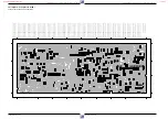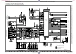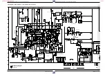
Abgleichvorschriften / Adjustment Procedures
GRUNDIG Service-Technik
3 - 5
2.2 Family Board – Frontend (FV)
Test equipment: Oscilloscope with 10:1 Test Probe, Voltmeter, Colour Generator
Service work after replacing the Family Board: Adjustments no. 1…3
Adjustment
Preparation
Adjustment Procedure
Set the voltage with F5703 (AFC) to 2.5V
±
0.2V.
Set the amplitude with R3724 (AGC) to 800mV
PP
±
0.2V.
Feed 38.9MHz / 100mV
rms
into the tuner output 1720-(17).
Voltmeter: ..................................................... IC7702-(15)
EE mode.
Feed in a standard test pattern (upper UHF-range, Ch25,
67dB
µ
V aerial signal) into a warmed-up set.
Set R3724 (AGC) to the "left stop" (wiper contact to ground).
Oscilloscope (input capacity
≤
2.5pF): ............ IC7702-(1)
EE mode.
1. Vision Demodula-
tor Circuit, F5703
2. Delayed AGC
Voltage, R3724
3. Tuning Range
– Erase the EEPROM IC7412: Press and hold the buttons "
rr
", "
ee
" and "
q
" while connecting the recorder to the
mains.
– Call up the service function: Press the "STOP" button on the remote control handset and the button "
e
" on the video
recorder simultaneously for approx. 5sec.
– Feed in a standard test pattern, VHF Ch 2 (48.25MHz) and start the station search mode.
– Store the lower tuning channel: Press the buttons "STOP" and "
rr
" simultaneously on the video recorder.
– Feed in a standard test pattern, UHF Ch 69 (855.25MHz), and start the station search mode.
– Store the upper tuning channel: Press the buttons "STOP" and "
ee
" simultaneously on the video recorder.
– Terminate the service function: Press the "Standby" button.
Service Work after this adjustment:
– 2.1 Sequence Control / Deck Electronic (DE) – Adjustment no. 1
1. EE-Level, R3010
2.1 Frequency
Deviation Sync
Value, R3018
2.2 White Value,
R3020
3. Record Current
3.1 Y Record
Voltage, R3099
3.2 Chroma Record
Current, R3096
4. Playback
Amplitude, R3039
Set amplitude with R3010 (E-E LEVEL) to 0.5V
PP
±
0.02V.
The voltage at the AV-socket-1, contact 19, must be 1.9V
pp
±
0.1V
Set frequency counter with R3018 (SYNC FREQ) to 3.8MHz
±
10kHz.
Set frequency counter with R3020 (WHITE FREQ) to
4.6MHz
±
10kHz.
Set FM signal with R3099 (LUMINANCE WRITING
CURRENT) to 260mV
PP
.
Set Chroma signal with R3096 (CHROMINANCE WRITING
CURRENT) to 50mV
PP
(-14dB of the FM-signal).
Set amplitude with R3039 (Y-PB LEVEL) to 1.8V
PP
±
0.05V.
2.3 Family Board – Video/Chroma (VS)
Test equipment: Oscilloscope with 10:1 Test Probe, Frequency Counter, Colour Generator
Service work after replacing the Family Board: –
Adjustment
Preparation
Adjustment Procedure
Feed in a white test pattern (100%).
Oscilloscope: .................................................. IC7501-(4)
EE mode.
Do not feed in an aerial signal.
Record.
Frequency counter:
...................... Head Amplifier TP1 (Video current testpin)
Check the Adjustment 1. EE-Level and 2.1 Frequency
Deviation Sync Value.
Feed in a white test pattern (100%).
Record.
Frequency counter:
...................... Head Amplifier TP1 (Video current testpin)
The two adjustments 3.1 Y-Record Current and 3.2 Chro-
ma Record Current must be carried out together.
Do not feed in an aerial signal.
Oscilloscope: Head Amplifier TP1 (Video current testpin)
Record.
Connect IC7501-(40) to +5V.
Feed in a red raster test pattern with 75% saturation
(ratio burst : chroma = 1 : 2.2).
Oscilloscope: Head Amplifier TP1 (Video current testpin)
AV recording.
Disconnect IC7501-(40) from +5V.
Playback a white test pattern (recorded with the machine)
Oscilloscope: .................... EURO-AV socket, contact 19
www.freeservicemanuals.info
It`s Free


