GV 411-2
Abgleich / Adjustment Procedures
GRUNDIG Service
3 - 5
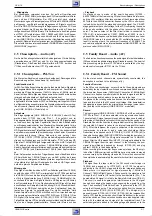
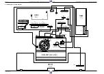
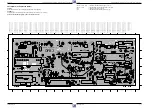
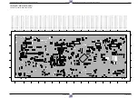
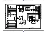
2.2 Family Board – Frontend (FV)
Test equipment: Oscilloscope with 10:1 Test Probe, Voltmeter, Colour Generator
Service work after replacing…
… the Tuner: Adjustment no. 2
… the IC7201: Remove R3743 – the demodulator changes automatically to a default value.
Adjustment
Preparation
Adjustment Procedure
1. Vision Demodula-
tor Circuit, F5725
2. Delayed AGC
Voltage, R3742
3. Audio Level
4. Audio Crosstalk
Feed in 38.9MHz / 100mV
PP
into the tuner output 1701-(17).
Voltmeter: ..................................................... IC7201-(15)
EE-mode.
Feed in a PAL white test pattern with sound carrier (without
sound modulation, UHF-range, Ch24, 67dB
µ
V aerial signal)
into the warmed-up VCR.
Oscilloscope: ......................................... Tuner 1701-(17)
EE-mode.
Feed in a PAL white test pattern with sound carrier ("Ste-
reo" sound modulation, 1kHz sine,
±
27kHz deviation).
AF millivoltmeter: ................ EURO-AV1 socket, contact 1
EE-mode.
Call up the Service Function: Press the "STOP" button on
the remote control and then the "play" button on the video
recorder and hold them down for at least 5 s.
Feed in a PAL white test pattern with sound carrier ("Ste-
reo" sound modulation, 1kHz sine,
±
27kHz deviation).
AF millivoltmeter: ................ EURO-AV1 socket, contact 3
EE-mode.
Call up the Service Function: Press the "STOP" button on
the remote control and then the "play" button on the video
recorder and hold them down for at least 5 s.
Set the voltage with F5725
(AFC)
to 2.5V
±
0.2V.
Set the amplitude with R3742
(AGC)
to 550mV
PP
+0/-50mV.
Press the "pause/stop" button on the video recorder and
hold it down during the total adjustment process.
With the " – " or " + " button on the video recorder set the
output voltage to 0.5V
rms
±
50mV. Whenever one of these
buttons is pressed the voltage changes by 0.5dB and the
set value is stored in the EEPROM.
Terminate the Service Function by pressing button "standby".
Press the "pause/stop" button on the video recorder and
hold it down during the total adjustment process.
Press the button
F
or
G
to set the noise amplitude of
the left channel to Minimum. The set value is stored in the
EEPROM each time one of these buttons is pressed.
Terminate the Service Function by pressing button "standby".
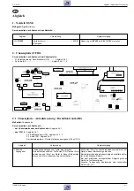
2.3 Family Board – Video/Chroma (VS)
Test equipment: Oscilloscope with 10:1 Test Probe, Frequency Counter, Colour Generator
Service work after replacing the Family Board: –
Adjustment
Preparation
Adjustment Procedure
Set frequency with R3054
(Sync. Frequ.)
to 3.8MHz
±
10kHz.
Set Chroma signal with R3038
(PAL Curr.)
to 71mV
PP
(-12.5dB
of the FM-signal).
Disconnect IC7051-(2) from +5V.
Frequency counter: ............................................ 1911-(2)
AV recording (do not feed in a signal).
Connect IC7051-(2) to +5V.
Oscilloscope: ...................................................... 1911-(2)
Feed in a PAL red raster test pattern with 75% saturation
(ratio burst : chroma = 1 : 2.2).
AV recording.
1. Frequency
Deviation Sync
Value, R3054
2. Chroma Writing
Current, R3038

