background image

27599-002.55

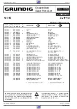
Ersatzteilliste / Spare Parts List

GRUNDIG Service

E - 13

ÄNDERUNGEN VORBEHALTEN

SUBJECT TO ALTERATION

Ersatzteilliste
Spare Parts List

SACH-NR. / PART NO.:  27599-002.55

12 / 95

BEDIENPLATTE ODCE 1/STEREO 7H

CONTROL BOARD ODCE 1/STEREO 7H

D

 Btx 

*

 32700 

#

POS. 

NR.

ABB.

SACHNUMMER

ANZ.

POS. 

NO.

FIG.

PART NUMBER

QUA.

BEZEICHNUNG

DESCRIPTION

D

GB

0006.000

75988-032.51

HALTER, DISPLAY

HOLDER, DISPLAY

1101.000

75988-000.91

STECKERLEISTE 15P

MULTIPOINT CONNECTOR 15P

7102.000

75988-324.29

DISPLAY 14 BT 37 GK

DISPLAY 14 BT 37 GK

7103.000

75988-000.69

IR-EMPFAENGER TFMS 5360

IR REC CONTR TFMS 5360

BEZEICHNUNG

DESCRIPTION

SACHNUMMER

PART NUMBER

POS. 

NR.

POS. 

NO.

BEZEICHNUNG

DESCRIPTION

SACHNUMMER

PART NUMBER

POS. 

NR.

POS. 

NO.

C 2003

8672-160-122

KEFQ 0805  10PF  5%

C 2004

8672-160-124

KEFQ 0805  15PF  5%

C 2005

8699-999-356

TR.15  7,5/50PF  VCT 56

C 2010

75988-001.36

SMD KONDENS.10N PM10X7R

C 2011

75988-324.39

ELKO 6,3V 220MU

C 2020

75988-007.15

ELKO 22MU 16V PM20 7MM

C 2030

75988-001.36

SMD KONDENS.10N PM10X7R

C 2031

8672-167-270

KEFQ 0805  0,1  UF 10%

C 2032

8672-167-270

KEFQ 0805  0,1  UF 10%

C 2037

75988-001.36

SMD KONDENS.10N PM10X7R

C 2051

75988-028.82

KOND.CER2 0805 Y5V 100N

C 2997

75988-002.14

KONDENS.5,5V 220M

D 6031

8309-214-218

DIODE TD129 UNI/1N4148/BA

D 6032

8309-214-218

DIODE TD129 UNI/1N4148/BA

D 6050

75988-009.33

DIODE BZX 79 C 9 V 1

D 6093

8309-214-218

DIODE TD129 UNI/1N4148/BA

D 6094

8309-214-218

DIODE TD129 UNI/1N4148/BA

D 6095

8309-214-218

DIODE TD129 UNI/1N4148/BA

D 6096

8309-214-218

DIODE TD129 UNI/1N4148/BA

D 6097

8309-214-218

DIODE TD129 UNI/1N4148/BA

D 6099

8309-198-542

DIODE BAT42/43/BAT85/86

IC 7101

75988-033.32

OTPROM ODCE2-1U/6379

L 5000

75988-002.17

SPULE 22MUH

Q 1001

75988-009.75

CER.RES.8MHZ CST 8.00 MTW

Q 1002

75988-005.01

QUARZ 32,768 KHZ

R 3011

8706-100-097

R-CHIP 0805  10 KOHM  5%

R 3012

8706-297-089

R-CHIP 1206 4,7 KOHM  5%

R 3028

8706-100-057

R-CHIP 0805 220  OHM  5%

R 3029

8706-100-097

R-CHIP 0805  10 KOHM  5%

R 3030

8706-297-105

R-CHIP 1206  22 KOHM  5%

R 3031

8706-100-089

R-CHIP 0805 4,7 KOHM  5%

R 3032

8706-100-073

R-CHIP 0805  1 KOHM  5%

R 3033

8706-100-081

R-CHIP 0805 2,2 KOHM  5%

R 3034

8706-100-089

R-CHIP 0805 4,7 KOHM  5%

R 3035

8706-297-097

R-CHIP 1206  10 KOHM  5%

R 3036

75988-000.74

WIDERST.1/8W 10KOHM PM5

R 3037

8706-100-105

R-CHIP 0805  22 KOHM  5%

R 3050

75988-000.76

KSW 0203 4,7 KOHM 5% AX

R 3051  

S

75988-010.87

SI.-WIDERST.22 OHM ERD6FC

R 3053

75988-009.29

WIDERST.15 OHM 5%

R 3300

8706-100-097

R-CHIP 0805  10 KOHM  5%

R 3301

8706-297-085

R-CHIP 1206 3,3 KOHM  5%

R 3302

8706-100-085

R-CHIP 0805 3,3 KOHM  5%

R 3303

8706-297-049

R-CHIP 1206 100  OHM  5%

R 3304

8706-297-049

R-CHIP 1206 100  OHM  5%

R 3305

8706-297-049

R-CHIP 1206 100  OHM  5%

R 3306

8706-100-049

R-CHIP 0805 100  OHM  5%

R 3307

8706-100-049

R-CHIP 0805 100  OHM  5%

R 3308

8706-100-049

R-CHIP 0805 100  OHM  5%

R 3900

8706-297-000

R-CHIP 1206  JUMPER

R 3901

8706-297-000

R-CHIP 1206  JUMPER

R 3902

8706-297-000

R-CHIP 1206  JUMPER

R 3903

75988-011.49

CHIP-JUMPER 0805 MAX 0R05

R 3905

8706-297-000

R-CHIP 1206  JUMPER

R 3910

8706-297-000

R-CHIP 1206  JUMPER

R 3914

8706-297-000

R-CHIP 1206  JUMPER

R 3991

75988-011.49

CHIP-JUMPER 0805 MAX 0R05

R 3992

75988-011.49

CHIP-JUMPER 0805 MAX 0R05

S 1014

75988-000.63

TIPPTASTE

S 1019

75988-000.63

TIPPTASTE

S 1022

75988-000.63

TIPPTASTE

S 1032

75988-000.63

TIPPTASTE

S 1033

75988-000.63

TIPPTASTE

S 1034

75988-000.63

TIPPTASTE

S 1035

75988-000.63

TIPPTASTE

S 1039

75988-000.63

TIPPTASTE

S 1042

75988-000.63

TIPPTASTE

S 1043

75988-000.63

TIPPTASTE

S 1045

75988-000.63

TIPPTASTE

S 1049

75988-000.63

TIPPTASTE

S 1053

75988-000.63

TIPPTASTE

S 1054

75988-000.63

TIPPTASTE

S 1055

75988-000.63

TIPPTASTE

S 1059

75988-000.63

TIPPTASTE

T 7030

8301-006-858

SMD-TRANS.BC 858 C

T 7031

8301-004-848

SMD-TRANS.BC 848 B

Summary of Contents for GV 411-2

Page 1: ...Part No 72010 524 15 VIDEO SERVICE MANUAL D Btx 32700 Service Manual Sicherheit Safety Sach Nr Part No 72010 800 00 Zus tzlich erforderli che Unterlagen f r den Komplettservice Additionally required S...

Page 2: ...coder ONIC 4 34 Head Amplifier Board OHA 4 37 Head Amplifier 4 38 Headwheel Motor Control 4 39 Keyboard Control Unit ODCE1 4 41 Oscillograms 4 45 Drive Mechanism 5 1 5 12 Test Equipment Jigs 5 1 Servi...

Page 3: ...26 S P 4 37 Kopfverst rker Head Amplifier OHA 27599 004 19 S P 4 41 Bedieneinheit Keyboard Control Unit ODCE1 27599 002 55 CCIR I PAL NICAM 6 Kopf Head 4 Video 2 Audio HiFi Stereo Normalplay Longplay...

Page 4: ...1011 Test cassette HiFi 9 27540 1016 Torquemeter 600gf cm 75987 262 72 Adapter 75987 262 73 Adjustment screw driver 75987 262 80 Tape tension adjustment tool handle and pin 75988 002 27 Headwheel extr...

Page 5: ...nenausgangsbuchse 4 Kanaleinsteller x II EXT 2 EXT 1 store search set clock record eject pause stop II play speed speed standby Schaltet den Recorder ab Standby Zur Tonspurwahl Ohne Funktion TIMER Pro...

Page 6: ...ial output socket 4 Channel adjuster x II EXT 2 EXT 1 store search set clock record eject pause stop II play speed speed standby Switch off Audio track selection No function TIMER programming with Sho...

Page 7: ...die Cassettenklappe so nach innen zu dr cken da der Hebel E in die F hrung Fig 4 der Cassetten klappe eintaucht Service Instructions 1 Removing the Cabinet Parts 1 1 Cabinet Upper Part Undo 7 screws...

Page 8: ...cable between the tuner and the modulator is connected for safety reasons VDE the cover of the modulator is fitted Carry out the alignment procedures described in chapter 3 Fig 6 Fig 5 H H 2 3 Netzte...

Page 9: ...to remove it Fig 10 2 5 Removing the Drive Mechanism Remove the Family Board Release the locking catch Q Fig 10 and remove the tape deck holder Release the locks R Fig 8 and S Fig 9 of the cassette c...

Page 10: ...of production Type Plate Advice Important changes are indicated by increasing the change code by one 1 TYPE GV 411 2 Produktionscode Production code Ger tetype Type of product Seriennummer Serial numb...

Page 11: ...nce control computer and the keyboard control computer Level 2 Tape deck sensors Level 3 Error status and error code Level 4 Operating hours meter The levels can be changed step by step by pressing th...

Page 12: ...Cassette in Wiedergabe Play Einf deln Thread in Cassette unten Cassette down Index Umsspulen Index wind rewind 1 3 Level 3 of the Service Test Programme Error Codes and Error Status The last error cod...

Page 13: ...etestprogramm Ebene 1 Kontrolle der Optionscodes Optionscodeeingabe A aufrufen siehe oben Durch Dr cken der Taste store am Ger t ohne vorheriger Optionscode Eingabe ist die Kontrolle der Optionscodes...

Page 14: ...das Ger t die Dauerlaufpr fung entspre chend dem folgenden Schema Beenden der Dauerlaufpr fung Taste STANDBY dr cken oder Ger t vom Netz trennen Aufnahme Record Wiedergabe Play Bandanfang Beginning of...

Page 15: ...the blocking oscillator transformer is connected to the rectified mains voltage C2070 During the conducting phase of the transistor energy is stored in the transformer which is fed to the secondary wi...

Page 16: ...on with the phase voltages At the output IC7301 6 there are the PG phase generator pulses of 25Hz for the phase control and also the FG frequency generator pulses of 450Hz for the speed control From t...

Page 17: ...gef hrt Die Impulse FG vom Capstanmotor Treiber IC LB1887 Pin 3 f r die Drehzahlregelung werden ber Steckerkontakt 1913 2 IC7411 8 dem internen Komparator und IC7411 11 dem IC7410 19 zugef hrt Die Tac...

Page 18: ...ignals are selected according to the operating mode and fed to the circuit sections Video Chroma VBS and the output sockets EURO AV1 VOUT1 and EURO AV2 VOUT2 respectively The audio signals are distrib...

Page 19: ...rkerstufe T7022 Von dort gelangt es ber den IN OUT Schaltungsteil zu der Buchse EURO AV 1 und zum Modulator Record Signal Path The CCVS signal VBS selected by the IN OUT circuit stage is fed from pin...

Page 20: ...internen 5 06MHz Bandpa SUB BPF und wird anschlie end dem Hauptmi scher MAIN CONV zugef hrt 2 4 2 Family Board Chroma Function Overview On record the 4 43MHz chroma signal is converted to 627kHz with...

Page 21: ...l vom Band wird dem FM Ton Schaltungsteil ber 1905 6 zugef hrt und an IC7100 57 weitergeleitet Im IC7100 durchl uft es die HF AGC Stufe und in den integrierten Bandpa Filtern trennt man es f r die Sig...

Page 22: ...f r den Haupt und Tonl schkopf besteht aus dem Transistor T7609 und dem Resonanzkreis F5603 C2622 Von diesem wird auch die Vormagnetisierungsspannung BIAS abgeleitet Die Ansteuerung des Oszillators e...

Page 23: ...swertung 2 Monokan le Zweiton 1 Mono kanal 1 Datenkanal Stereo und NICAM Ton Analogton erfolgt im Controller Interface des IC7000 3 NICAM Decoder ONIC General Information on NICAM The NICAM NEAR INSTA...

Page 24: ...el so da weitere Funktionen des ICs mit dem Systemquarz Q1001 an Pin 13 14 abgeschaltet werden 4 Keyboard Control Unit ODCE1 ThemicrocomputerIC7101istheheartofthekeyboardcontrolunitand takes over the...

Page 25: ...atte oder der Kopfscheibe Abgleich Nr 1 des IC7412 Abgleich Nr 1 2 2 Empfangseinheit FE Abgleich Nr 3 4 2 3 Audio AF Abgleich Nr 2 Servicetestprogramm Ger te Optionscode eingeben Punkt 1 5 2 Abgleich...

Page 26: ...67dB V in betriebswarmes Ger t einspeisen Oszilloskop Tuner 1701 17 EE Betrieb PAL Wei testbild mit Tontr ger Tonmodulation Stereo 1kHz Sinus 27kHz Hub einspeisen NF Millivoltmeter EURO AV1 Buchse Ko...

Page 27: ...requenz F5603 1 1 Vormagneti sierung R3618 1 2 Frequenzgang pr fung 2 Standardton Wiedergabepegel Frequenz mit F5603 Erase Oscillator auf 70kHz 10kHz einstellen Spannungsabfall an R3600 mit R3618 BIAS...

Page 28: ...ly Board or Headwheel Adjustment no 1 IC7412 Adjustment no 1 2 2 Frontend FE Adjustment no 3 4 2 3 Audio AF Adjustment no 2 Service Test Programme Entering the VCR Option Code para 1 5 2 Adjustment Pr...

Page 29: ...utton on the video recorder and hold them down for at least 5 s Set the voltage with F5725 AFC to 2 5V 0 2V Set the amplitude with R3742 AGC to 550mVPP 0 50mV Press the pause stop button on the video...

Page 30: ...Frequency counter 1918 7 Record AF millivoltmeter R3600 Record Feed an audio signal of 200mVrms 480mVPP from the AF generator to the EURO AV1 socket contact 2 or 6 Make a recording of 400Hz and 8kHz e...

Page 31: ...t 1 links rechts Audio input scart 1 left right IO AF AIN2L R Audio Eingang von Scart 2 links rechts Audio input scart 2 left right IO AF OIO ALLI ARLI Audiopegel links rechts Audio level left right D...

Page 32: ...2 IO OIO NAL NAR NICAM Audio links rechts NICAM audio left right ONI NC Nicht verwendet Not connected DE NSM Netzteil Power Supply NSM OIO IN OUT Zusatzplatte IN OUT Subpanel OIO ONI NICAM Decoder NIC...

Page 33: ...2 MEH1 1 2 1 2 3 7 6 4 3 2 1 5 1 1 ERASE HEAD AUDIO CONTROL HEAD THREADING MOTOR HEAD AMPLIFIER 8009 Tuner GND APH AEH2 AEH1 CTL2 CTL1 ARH 1 1 7 6 4 3 2 1 5 red 8SC2 green pin10 blue 9 8 7 6 10 AIN2L...

Page 34: ...Schaltpl ne Layout of PCBs and Circuit Diagrams GV 411 2 Platinenabbildungen und Schaltpl ne Layout of PCBs and Circuit Diagrams GV 411 2 4 5 GRUNDIG Service 4 6 GRUNDIG Service Blockschaltplan Block...

Page 35: ...V 411 2 Platinenabbildungen und Schaltpl ne Layout of PCBs and Circuit Diagrams GV 411 2 Platinenabbildungen und Schaltpl ne Layout of PCBs and Circuit Diagrams GRUNDIG Service 4 7 GRUNDIG Service 4 8...

Page 36: ...ltpl ne Layout of PCBs and Circuit Diagrams GV 411 2 Platinenabbildungen und Schaltpl ne Layout of PCBs and Circuit Diagrams GV 411 2 Blockschaltplan Block Circuit Diagram Digital 4 9 GRUNDIG Service...

Page 37: ...0 8 B 8001 7 B 8002 6 B 8003 6 B 8004 6 B 8005 1 B 8006 2 C 8007 1 C 8008 3 C END 3 1 1 2 4 0 3 3 0 4 1 5 8 2 1 2 1 6 0 0 0 4 1 5 D 5042 2104 2102 5160 1 4 5 8 7005 4 2 12 14 1509 3011 3007 1 3 4 6 70...

Page 38: ...par Stop Logik wachung ueber spg Speise quelle Strom u verst Ueberl Regel detekt durchg Null typ 3V SPG Refer SPH4690 18 17 16 15 14 13 12 11 10 9 8 7 6 5 4 3 2 1 Y 7007 6 5 4 3 2 1 12 11 10 9 8 7 15...

Page 39: ...15 9022 C 11 9023 B 5 9024 D 13 9025 A 11 9026 C 12 9027 E 13 9029 D 3 9030 D 13 9031 D 5 9032 D 14 9033 D 12 9035 D 14 9036 B 11 9037 B 8 9038 C 5 9039 B 15 9041 B 1 9042 B 4 9043 B 11 9044 E 14 9046...

Page 40: ...961 E 8 3966 A 3 3980 D 5 3982 A 3 3983 E 4 3984 C 11 3985 D 8 3986 E 9 3987 D 14 3988 E 9 3990 E 11 3991 E 12 7000 B 9 7007 A 9 7009 D 11 7010 A 10 7011 D 11 7012 A 9 7013 C 10 7014 C 9 7015 C 10 701...

Page 41: ...BOARD DECK ELECTRONICS DE 1913 n c SW1 K 9 7106 N 6 7104 E 9 7103 C 9 7102 A 6 6103 G 8 3602 E 9 3601 E 8 3600 D 9 3501 K 8 3401 L 6 3300 D 6 3202 D 5 3201 D 5 3200 D 5 1969 H10 1967 M 1 1965 F 2 160...

Page 42: ...1 7 8 9 10 11 12 13 14 15 16 17 2 18 19 20 21 22 23 3 M L K P J I H G F E D C B A O N M L K P J I H G F E D C B A O N 4 5 6 1 7 8 9 10 11 12 13 14 15 16 17 2 18 19 20 21 22 23 3 5VA 33V 28V 12A HSC2 E...

Page 43: ...H19 3923 H15 4 5 6 1 7 8 9 10 11 12 13 14 15 16 17 2 18 19 20 21 22 23 3 H G F K E D C B A J I H G F K E D C B A J I 4 5 6 1 7 8 9 10 11 12 13 14 15 16 17 2 18 19 20 21 22 23 3 1k 3764 3919 0E 3918 0...

Page 44: ...G13 2515 F13 2514 F13 2513 F13 2512 F11 2511 H15 2510 H15 2500 I 7 1917 A 1 1591 A16 1501 G 7 1500 I 9 4 5 1 6 7 8 9 10 11 12 13 14 15 16 2 3 H G F K E D C B A J I H G F K E D C B A J I 4 5 1 6 7 8 9...

Page 45: ...18p 2024 22p 2049 47n 2003 100n 2006 22n 2001 10n 2007 47n 2004 330p 2014 10n 2012 10n 2019 100p 2051 1n 2043 100n 2038 47p 2042 27p 2041 68p 2040 68p 2039 560p 2055 27p 2054 33p 2053 82p 2035 56p 203...

Page 46: ...20E 3112 220E 3110 220E 3111 3M3 3608 2k2 3601 100E 3122 100E 3121 100k 3650 10k 3127 47k 3126 3139 100E 3617 22k 47E 3600 100k 3651 2k2 3652 220E 3616 3106 8k2 3M3 3607 220E 3615 22k 3109 18k 3108 31...

Page 47: ...2 5112 B 2 5113 B 1 5114 B 2 6540 A 5 6550 A 3 6560 A 3 6561 C 5 6562 B 5 6563 B 4 6564 B 3 6570 A 5 6571 B 5 6590 A 4 7151 B 1 7850 C 4 9001 C 5 9002 A 3 9003 B 3 9004 A 2 9005 B 4 9006 C 2 9007 C 3...

Page 48: ...ZX79 C12 6550 BZX79 C12 6590 BZX79 C18 6570 BZX79 C12 6571 BZX79 C12 6560 BZX79 C12 6580 BZX84 C12 6561 BZX79 C12 6562 BZX79 C12 6563 BZX79 C12 6564 BZX79 C18 6565 BZX84 C6V8 6566 BZX84 C6V8 GNDA GNDA...

Page 49: ...B A J I H G F K E D C B A J I 4 5 1 6 7 8 9 10 11 12 13 14 15 16 2 3 GNDA GNDA GNDD GNDD GNDD GNDD GNDD GNDA1 GNDD GNDA2 GNDA2 GNDA GNDA GNDA GNDA GNDA GNDA GNDA GNDA2 GNDA2 GNDA2 GNDA2 GNDA1 GNDA1 GN...

Page 50: ...1 2314 2u2 7301 15 9 10 11 12 18 7 17 1 3 16 6 5 2 4 13 14 PROTECT THERMAL DEVIDE BY 2 STAGE2 DRIVER OUTPUT STAGE1 DRIVER OUTPUT FLYBACK PUSH PULL ROTATION POSITION SPEED DETECTOR STAGE OUTPUT STAGE P...

Page 51: ...6 7 8 9 10 11 12 13 14 15 16 2 3 H G F K E D C B A J I H G F K E D C B A J I 4 5 1 6 7 8 9 10 11 12 13 14 15 16 2 3 0E 3014 0E 3013 0E 3006 0E 3005 0E 3003 0E 3004 100E 3107 100E 3011 1k 3103 4k7 310...

Page 52: ...ODCE1 S T B Y RE C UP 1 2011 9 0 1 0 5 0 0 0 6 0 9 9 9 0 0 5 9 0 0 4 6031 9001 2997 9014 9 0 0 8 9 0 1 2 3 0 3 6 1001 1 0 0 2 2005 3003 6032 9000 2020 2999 2998 9002 3998 6998 7102 7103 3053 9 0 0 7 3...

Page 53: ...1022 1055 1032 1042 1049 1043 1034 1033 1045 1035 1039 1054 1053 1N4148 6031 6099 BAT85 6097 1N4148 6096 1N4148 1N4148 6095 1N4148 6094 1N4148 6093 14 BT 37GK 7102 36 35 34 33 32 45 44 43 42 41 40 39...

Page 54: ...v 20 s Div 2 3V IC7051 38 21 REC AC 100mV Div 20 s Div 3 2V IC7051 38 21 PB AC 200mV Div 200ns Div Tuner 1701 17 26 REC AC 500mV Div 500 s Div IC7201 9 27 REC AC 200mV Div 20 s Div 1 6V T7721 Emitter...

Page 55: ...a high repair standard we have developed a range of service kits A B C These kits cover all important spare parts which engage with each other The position numbers Pos in this description are also spe...

Page 56: ...befestigt Cassettenschacht Scanner Capstanmotor Kombikopf Anmerkung Bei einer nderung der Position des Cassettenschachtes Lift w h rendderReparaturmu dieserdanachvonHandindiePosition Eject gebracht we...

Page 57: ...eite entfernen Frontblende entfernen Servicehinweise Kap 1 beachten und Cassettenschacht abheben Vorbereitung f r den Einbau Der Cassettenschacht und das Laufwerk m ssen sich beim Einbau in einer best...

Page 58: ...Pos 103L is released if it is not the drive gear of the threading motor must be turned to release it Put on the cassette compartment Fastenthecassettecompartmentwiththe4screws A Fig 5 atthe bottom Pla...

Page 59: ...el Fig 9 Turn the lever by 90 in the direction of the arrow OPEN and remove the headwheel together with the lower clamping element Fig 10 Fig 7 A B 2 3 Kopfscheibe Hinweis Zum Ausbau der Kopfscheibe b...

Page 60: ...ellen siehe Abgleich Kap 3 Bandlauf kontrollieren siehe Punkt 3 1 Installation Before fitting the new headwheel make sure that the motor spindle is clean and undamaged the spindle should be free of gr...

Page 61: ...rnen Fig 15 und den Stecker des F delmotors abziehen F delmotor Pos 38 aus dem Motorhalter Pos 40M ziehen Fig 15 Beim Einbau darauf achten da der F delmotor vorne und hinten eingerastet ist 2 6 Capsta...

Page 62: ...o the Eject position Unhook the tension arm spring pos 11 to avoid the tension arm spring being pre loaded At the bottom side of the tape deck partially unhinge the sensor print and remove the tension...

Page 63: ...Pos 118 Bei einem Fehler auf der Laufwerkplatte Sensoreneinheit ist diese komplett zu tauschen Rastnasen l sen alle Platinen Laufwerkplatte Sensoreneinheit mit Spreizanker A Fig 20 heraushebeln und P...

Page 64: ...Servicetestprogramm verlassen durch Dr cken der Taste Stand by oder durch Trennen des Ger tes vom Netz 3 1 1 Threading Roller Unit Left Right Coarse adjustment Connect the 10 1 test probes of the dual...

Page 65: ...ebenenfalls mehrmals durchgef hrt werden 3 2 Einstellung des X Abstandes Servicetestprogramm aufrufen Die Tasten STOP auf der Fern bedienung und play am Ger t in dieser Reihenfolge dr cken und f r min...

Page 66: ...ntgegen dem Uhrzeigersinn so lange drehen bis der Wickelteller leicht durchrutscht Fig 28 Wert am Drehmomentmesser mu 7mNm 3mNm 70gf cm 30gf cm betragen 3 3 Brake Band Adjustment Lower the cassette co...

Page 67: ...loded Views GRUNDIG Service E 1 1 Explosionszeichnungen und Ersatzteilliste Exploded Views and Spare Parts List l Oil Sach Nr Part No 75988 002 35 Fett Grease Sach Nr Part No 75988 002 36 Isopropanol...

Page 68: ...Explosionszeichnungen Exploded Views GV 411 2 E 2 GRUNDIG Service 2 Fett Grease Sach Nr Part No 75988 002 36 Isopropanol Fusselfreies Tuch Fibrefree Tissue...

Page 69: ...zeichnungen Exploded Views GRUNDIG Service E 3 3 0008 000 0008 000 0008 000 0007 000 0004 000 0006 000 0005 000 0060 000 0050 000 0002 000 0003 000 0040 000 0001 000 0070 000 0019 000 0006 002 0006 00...

Page 70: ...3 S 27599 001 90 X CHASSISPL OFB32 4I KPL CHASSIS BOARD OFB32 4I ASSY 0060 000 3 S 27599 003 10 X NETZTEILPLATTE NSM 1E KPL POWER SUPPLY BOARD NSM 1E ASSY 0070 000 3 S 27599 002 55 X BEDIENPLATTE ODCE...

Page 71: ...000 1 75988 018 09 ROLLEREINHEIT RECHTS ROLLER UNIT RIGHT 0027 000 1 75988 001 25 B LADEZAHNRAD LOADING GEAR 0028 000 1 75988 018 11 M SENDER BANDABSCHALTUNG LIGHT PRISM 0029 000 1 75988 001 27 F INDE...

Page 72: ...88 001 30 I DOPPELRAD DOUBLE GEAR 0118 000 2 75988 018 22 SENSOR KPL SENSOR 0120 000 2 75988 018 11 M HEBEL CAM WHEEL LEVER 0125 000 2 75988 018 11 M HAUPTSCHIEBER MAIN SLIDER 0126 000 2 75988 018 15...

Page 73: ...0 400V C 2134 75988 005 91 ELKO 25V 680UF C 2185 75988 005 91 ELKO 25V 680UF C 2015 75988 010 66 KONDENS 100V 2N7 D 6027 8309 200 021 DIODE BAV 21 ITT D 6040 8309 516 852 DIODE BYT 52 M D 6070 75988 0...

Page 74: ...44 ELKO 10MU 16V PM 20 7MM C2024 8672 160 125 KEFQ 0805 18PF 5 C2026 75988 012 22 KERKO 390 P 2 C2027 75988 010 44 ELKO 10MU 16V PM 20 7MM C2028 75988 010 44 ELKO 10MU 16V PM 20 7MM C2029 75988 324 0...

Page 75: ...001 36 SMD KONDENS 10N PM10X7R C2611 75988 324 10 KONDENS CO805 22ON P80M20 C2612 8672 167 264 KEFQ 0805 0 033UF 10 C2613 8672 167 260 KEFQ 0805 0 015UF 10 C2614 75988 010 32 ELKO 1MU 50V PM20 7MM C2...

Page 76: ...R CHIP 0805 47 KOHM 5 R 3127 8706 100 097 R CHIP 0805 10 KOHM 5 R 3130 8706 100 121 R CHIP 0805 100 KOHM 5 R 3131 8706 100 121 R CHIP 0805 100 KOHM 5 R 3132 8706 100 121 R CHIP 0805 100 KOHM 5 R 3133...

Page 77: ...06 100 067 R CHIP 0805 560 OHM 5 R 3747 8706 100 059 R CHIP 0805 270 OHM 5 R 3760 8706 100 069 R CHIP 0805 680 OHM 5 R 3762 8706 100 073 R CHIP 0805 1 KOHM 5 R 3765 8706 100 073 R CHIP 0805 1 KOHM 5 R...

Page 78: ...72 160 122 KEFQ 0805 10PF 5 C 2703 8672 167 270 KEFQ 0805 0 1 UF 10 C 2704 8672 160 138 KEFQ 0805 220PF 5 C 2705 75988 010 44 ELKO 10MU 16V PM 20 7MM C 2706 75988 010 44 ELKO 10MU 16V PM 20 7MM C 2707...

Page 79: ...8 KHZ R 3011 8706 100 097 R CHIP 0805 10 KOHM 5 R 3012 8706 297 089 R CHIP 1206 4 7 KOHM 5 R 3028 8706 100 057 R CHIP 0805 220 OHM 5 R 3029 8706 100 097 R CHIP 0805 10 KOHM 5 R 3030 8706 297 105 R CHI...

Page 80: ...68 GRUNDIG ITALIANA S P A Via G B Trener 8 Trento 00 39 461 89 31 11 GRUNDIG SVENSKA AB Albygatan 109 d Box 4050 Solna 00 46 8 6 29 85 30 GRUNDIG DANMARK A S Lejrvej 19 V rl se 00 45 44 48 68 22 SF 02...

Reviews: