GV470S…
Servicehinweise / Service Instructions
GRUNDIG Servicetechnik
1 - 67
Service Instructions
1. Removing the Cabinet Parts
1.1 Cabinet Upper Part
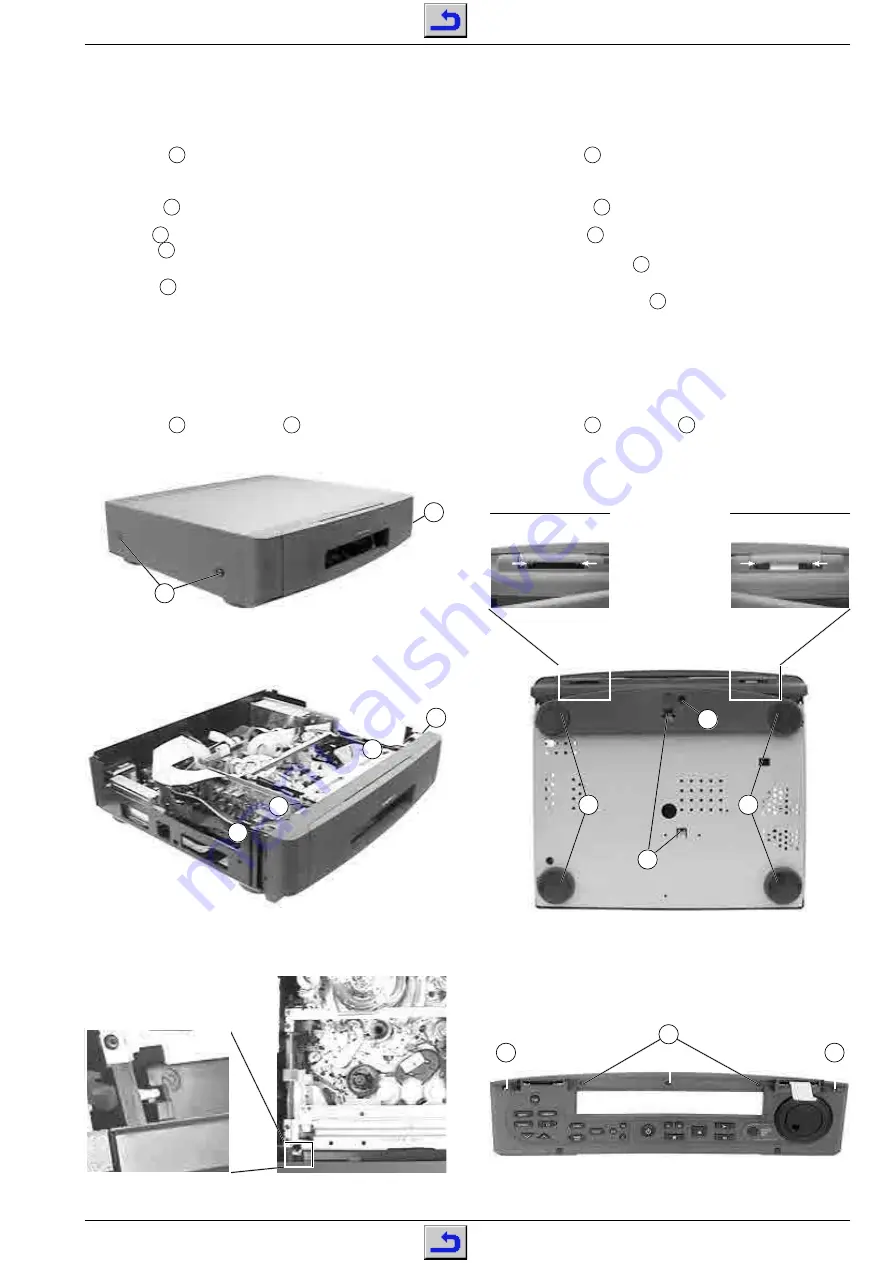
– Undo 4 screws
A
(Fig. 1).
– Lift off the cabinet upper part.
1.2 Bottom Panel
– Remove 4 inserts
B
(Fig. 3), undo the screw lying below each insert
and remove the feet at the rear side.
– Undo the screw
C
(Fig. 3) and remove the bottom masking panel
covering the front feet.
– Release the locking lugs
D
(Fig. 3) and remove the bottom panel.
1.3 Front Panel
– Release the locking catches
E
(Fig. 2), remove the front panel and
unplug the connector if necessary.
Note: When attaching the front panel from the front to the video
recorder press the cassette lid inwards so that the lever engages
with the guide (Fig. 4) of the cassette lid.
1.3.1 Front Flap
– Push the 4 hinge pins in the direction of the arrows (Fig. 3).
– Open the front flap halfway and remove it.
– Undo 3 screws
F
and 2 screws
G
(Fig. 5).
– Remove the keyboard unit from the front flap.
Servicehinweise
1. Entfernen der Gehäuseteile
1.1 Gehäuseoberteil
– 4 Schrauben
A
herausdrehen (Fig. 1).
– Gehäuseoberteil abnehmen.
1.2 Bodenblech
– 4 Einlagen
B
(Fig. 3) abnehmen, die je darunter befindliche
Schraube herausdrehen und die hinteren Gerätefüße abnehmen.
– Schraube
C
(Fig. 3) herausdrehen und Fußblende abnehmen.
– Rastnasen
D
lösen (Fig. 3) und Bodenblech abnehmen.
1.3 Frontblende
– Rasthaken
E
(Fig. 2) lösen, Frontblende abnehmen und gege-
benenfalls Steckverbindung lösen.
Hinweis zum Zusammenbau: Beim Aufstecken der Frontblende
von vorne auf das Gerät ist die Cassettenklappe so nach innen zu
drücken, daß der Hebel in die Führung (Fig. 4) der Cassettenklappe
eintaucht.
1.3.1 Frontklappe
– 4 Scharnierstifte in die angegebene Richtung schieben (Fig. 3).
– Frontklappe halb öffnen und abnehmen.
– 3 Schrauben
F
und 2 Schrauben
G
herausdrehen (Fig. 5).
– Bedienfeld aus der Frontklappe nehmen.
Fig. 5
Fig. 2
Fig. 4
B
B
D
Fig. 3
Fig. 1
A
A
C
E
E
E
E
F
G
G


