M 100-CD MKII
Allgemeiner Teil / General Section
GRUNDIG Service
1 - 7
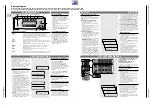
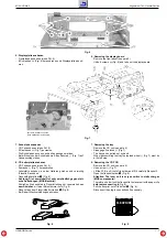
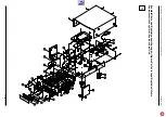
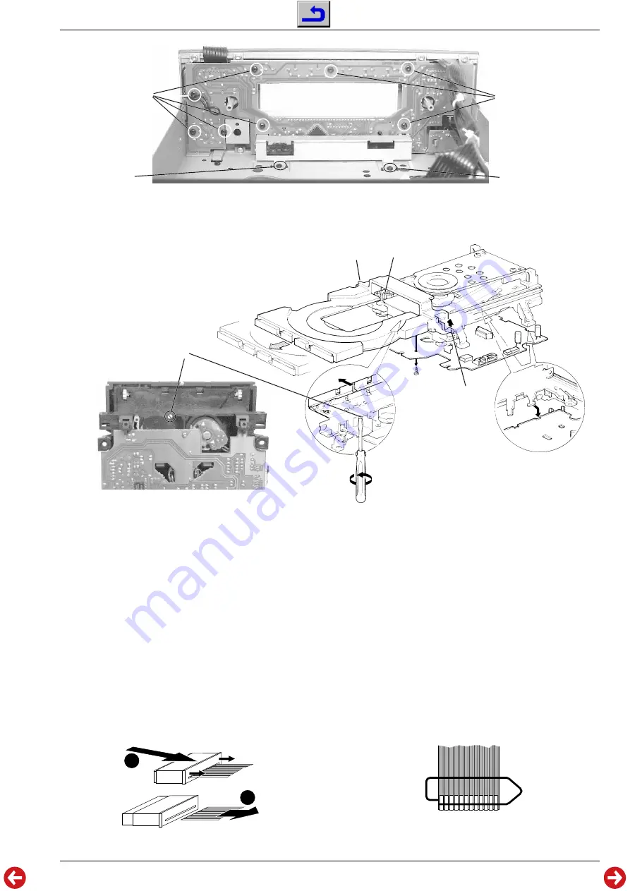
Fig. 6
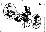
Fig. 7
6. Displayplatte ausbauen
- Frontblende ausbauen (siehe Pkt. 5).
- 8 Schrauben
Q
(Fig. 6) herausdrehen und Displayplatte abneh-
men.
7. Schublade ausbauen
- CD-Teil ausbauen (siehe Pkt. 4).
- 2 Rastnasen
R
(Fig. 7) ausrasten.
- Die Schublade kann nun nach außen gezogen werden.
- Beim Einsetzen der Schublade muß das Zahnrad
S
(Fig. 7) auf
Linksanschlag stehen.
8. CD-Leiterplatte ausbauen
- CD-Teil ausbauen (siehe Pkt. 4).
- Schraube
T
(Fig. 7) herausdrehen.
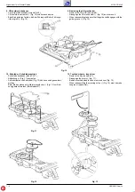
- Leiterplatte anheben, aus der Halterung ziehen und vorsichtig
(Flexprint!) anheben.
- Flexprinthalter öffnen
1
(Fig. 8).
- Achtung: Die Lasereinheit ist sehr empfindlich gegen stati-
sche Aufladungen (MOS-Bauteile)!
Schließen Sie deshalb die Flexprintleitung zur Lasereinheit vor
dem Abziehen mit einer Büroklammer kurz (Fig. 9).
- Flexprint aus dem Flexprinthalter ziehen
2
(Fig. 8).
- Bei Bedarf Steckverbindungen abziehen.
1
2
6. Removing the display board
- Remove the front panel (see para 5).
- Undo 8 screws
Q
(Fig. 6) and take out the display board.
7. Removing the tray
- Remove the CD unit (see para 4).
- Disengage 2 catches
R
(Fig. 7).
- The tray can be pulled out by hand.
- When reassembling the tray the toothed wheel
S
(Fig. 7) must be
at its left stop.
8. Removing the CD PCB
- Remove the CD unit (see para 4).
- Undo screw
T
(Fig. 7).
- Lift the PCB, pull it out of its holder and lift it carefully (flexprint!).
- Open the flexprint holder
1
(Fig. 8).
- Attention: The laser unit is very sensitive to static charges
(MOS components)!
Therefore, short-circuit the flexprint to the laser unit with a paper clip
before disconnecting it (Fig. 9).
- Pull the flexprint out of its holder
2
(Fig. 8).
- Disconnect the plug-in connections if necessary.
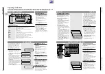
Fig. 8
Fig. 9
Q
Q
L
L
I
Laufwerk, Ansicht von unten
Drive mechanism, bottom view
R
R
S
T
FLEXPRINT


