background image

- 5 -

- 5 -

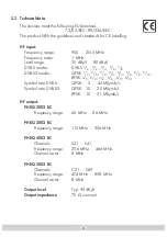
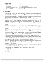
Connections: 

  SAT inputs:  


2 F-connectors

  HF output:  


1 IEC socket, female

  Connection strip (10-pin):


For supply voltages and control circuits

  Socket RS 232: 


Update interface 

2.3 Description

The Cassettes convert two QPSK-modulated data flows into one QAM-modu-
lated data flow. The Cassettes are controlled via the head end. Each Cassette 
has two inputs and one HF output, as well as an integrated multi-transport flow 
processor for stuffing, PID pass, drop and service filtering.
For these Cassettes, information from a barker channel can be added or ex-
changed with a transport flow (MTP function, Drop- and service filter). For this 
purpose, there are two autonomous reception tuners and one modulator on 
which the modified transport flow can be transmitted as a QAM-modulated 
signal.
The SDT and PAT tables are automatically generated. All data relevant to the 
operation of the Cassette is registered in a logbook with a maximum of 500 
entries. 
The operating software of the Cassette can be actualised via an external 9-pin 
SUB-D-socket, using a PC or notebook, (software “

BE-Flash

”) or settings in the 

channel strips “

A

” (service channel) and “

B

” (barker channel) of the Cassette 

(PC software “

MTP

”, component of software PSW 1000). You can find the cur-

rent operating software of the Cassettes on the website “

http://www.gss.tv

”.

The prepared input signals are transmitted to the HF output collector of the head 
end via the HF output socket. The output level of the Cassettes can be set with the 
level regulator (max. –20 dB) at the output collector of the head end. 
After the head end has been switched on, the software version of the control 
unit is displayed briefly in the two-line LC display and afterwards the type of 
Cassette of the first slot. 
Approximately five minutes after the last button has been pressed, the software 
version of the control unit is displayed. 
The Cassettes are designed for use in the following head ends:
– PSU 

12

– PSU 

8

– PGT 

8

Summary of Contents for PHDQ 2002 BC

Page 1: ...D 90471 Nuremberg Phone 49 0 911 703 8877 Fax 49 0 911 703 9210 Email info gss tv Internet http www gss tv Grundig SAT SystEms Assembly Instructions Assembly Instructions English PHDQ 2002 BC PHDQ 30...

Page 2: ...us at a glance 11 5 2 1 The menu of channel strip B 12 5 3 Cassette programming 13 Selecting the Cassette 13 Switching the channel strip 13 To query software versions 14 Setting the output channel onl...

Page 3: ...equately ventilated Do not cover the ventilation slots Beware of short circuits No liability is accepted for damage caused by faulty connection or inexpert handling Observe the relevant norms regulati...

Page 4: ...S2 modes QPSK 1 2 3 5 2 3 3 4 4 5 5 6 8 9 9 10 8PSK 3 5 2 3 3 4 5 6 8 9 9 10 Symbol rate DVB S QPSK 2 45 MSymb s Symbol rate DVB S2 QPSK 10 30 MSymb s 8PSK 10 31 MSymb s HF output PHDQ 2002 BC Frequen...

Page 5: ...n of the Cassette is registered in a logbook with a maximum of 500 entries The operating software of the Cassette can be actualised via an external 9 pin SUB D socket using a PC or notebook software B...

Page 6: ...vice information which can be changed using the TP module The individual functions Station filter Individual stations can be deleted This reduces the data rate and consequently the output symbol rate...

Page 7: ...QAM SR A FEC x 2 7 x SR E 64 QAM SR A FEC x 1 3 x SR E 32 QAM SR A FEC x 2 5 x SR E 16 QAM SR A FEC x 1 2 x SR E 4 QAM SR A FEC x 1 1 x SR E Example Output symbol rate 64 QAM FEC 3 4 Input symbol rate...

Page 8: ...ith the connections of the circuit board and the HF bus bar Fasten the Cassette with the 1 screws 3 2 Connecting the Cassette Connect the HF input cable with the input sockets INPUT A 2 channel strip...

Page 9: ...on the head end control unit The two line display of the control unit then shows the menus You can select the following main menu items with the button Cassette and channel strip Output channel LNB o...

Page 10: ...to analogue Cassettes Connect the test receiver to the TEST OUTPUT 1 of the head end Set the output channel of the Cassette see page 14 and adjust the TV test receiver to this channel Switch on the m...

Page 11: ...ed by a star are only possible in the channel strip A Kanalzug Channel strip A B t 10 s Ein On BE Remote PROFESSIONAL V 34 Box 1 S21 S41 DVB MTP S21 Bx 1A PHDQ 4002 VERSION V3 Bx 1A S21 OUTPUT 306 00...

Page 12: ...dB C N 9 6 OK Bx 1A S21 S41 DVB MTP S21 Kanalzug Channel strip A B Bx 1A S21 S41 DVB MTP S21 Kanalzug Channel strip A B M Bx 1A f 11836 INPUT 0 4 Bx 1A 27500 INPUT DVB S Bx 1A SR 6900 6531 STUFFING Bx...

Page 13: ...Bx 1A DVB MTP Bx Cassette box 1 Cassette 1 A Channel strip A S21 S41 Adjustable channel range Functions of the MTP module S21 Set channel Select the desired channel strip A or B with Bx 1A C5 12 S3 2...

Page 14: ...y pressing set the desired output channel The channel range that can be set depends on the type of Cassette used Frequency offset fine tuning Press and hold down the button until 0 also appears in the...

Page 15: ...of 8 MHz Channel Channel centre frequency MHz S 21 306 00 S 22 314 00 S 23 322 00 S 24 330 00 S 25 338 00 S 26 346 00 S 27 354 00 S 28 362 00 S 29 370 00 S 30 378 00 S 31 386 00 S 32 394 00 S 33 402 0...

Page 16: ...switch the modulator HF output on default setting Press the button The display shows OUTPUT LEVEL HF OUT Setting output level of the channel strips only Bx A Press the button OUTPUT LEVEL CONTROL app...

Page 17: ...OM is shown in the display Producing a QAM signal for testing only Bx A The Cassette generates a QAM signal for testing without there having to be an input signal In the second menu line the correspon...

Page 18: ...ow Thus an automatic monitoring of the QAM modulated out put signal is possible Use to select Ueberwachung or KDG Press the button The menu Setting the LNB oscillator frequency LNB Freq is activated S...

Page 19: ...R 27500 to be changed and set the symbol rate with the buttons Setting the DVB mode The Cassettes recognize the transmitted DVB mode and switch over between the normal QPSK mode DVB S and the DVB S2 m...

Page 20: ...l as the preceding settings of the Cassette in question Use the buttons to place the cursor under the number to be changed and set the input frequency with the buttons Press to adjust the input freque...

Page 21: ...page 13 cancels all settings that have not been saved Press the button The menu Setting the QAM modulation value QAM MODE is activated Setting the QAM modulation value only Bx A Setting the QAM mode...

Page 22: ...uttons to place the cursor under the number to be changed number 1 and set the symbol rate with the buttons The value set corresponds to the new output symbol rate Note Increase the value of number 1...

Page 23: ...tions of the MTP module are activated their status is shown in the second line of the display Box 1 S21 S41 DVB MTP S21 1 2 3 1 Position P station filter on 2 Position i PSI off M PSI on PSI and drop...

Page 24: ...Alterations reserved Technical data E O E by GSS GmbH 26032006...

Reviews: