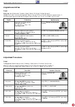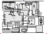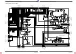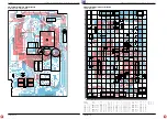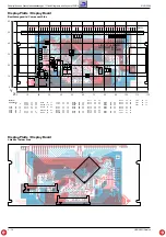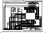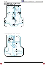
Abgleichvorschriften / Adjustment Procedures
RCD 2000
2 - 1
GRUNDIG Service
Abgleichvorschriften
Tuner
Messgeräte: Mess-/Wobbelsender, Oszilloskop, Digital-Voltmeter, NF-Voltmeter, Klirrfaktor-Messgerät
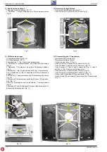
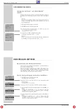
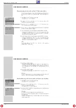
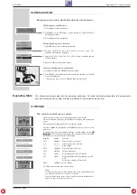
Hinweis: Das Frontend ist ein komplett abgeglichener Baustein. Nur das ZF-Filter muß dem ZF-Verstärker angeglichen werden (1).
Die Abstimmspannungen des Frontends haben folgende Größen: 87,5MHz = typ. 1,6V min 1,3V; 108MHz = typ. 8,0V max 9V
Abgleich
Vorbereitung
Abgleichvorgang
Mit
A
auf Maximum und Symmetrie
einstellen.
Mit F141
B
auf minimalen Klirrfaktor einstellen.
Mit P141
S
0,65V
±
0,05V einstellen.
Mit F171
I
(linker Kanal) und F172
K
(rechter Kanal)
Minimum einstellen.
Mit F171
G
(linker Kanal) und F172
H
(rechter Kanal)
Minimum einstellen.
1. ZF-Filter
2. Demodulator
3. Suchlauf
4. 38-kHz-Filter
5. 19-kHz-Filter
Wobbelsender an Antennenbuchse.
Mittenfrequenz 98MHz.
∆
f =
±
100kHz; U
HF
= 100
µ
V / 75
Ω
.
Oszilloskop an MP1.
Messsender 98MHz an Antennenbuchse.
U
HF
= 1mV / 75
Ω
, f
mod
= 1kHz, Hub = 40kHz.
Klirrfaktor-Messgerät an MP2.
Messsender 98MHz an Antennenbuchse.
U
HF
= 15
µ
V / 75
Ω
.
Digitalvoltmeter an MP5.
Messsender an Antennenbuchse.
U
HF
= 1mV / 75
Ω
, f
mod
= 38kHz, Hub = 40kHz.
NF-Voltmeter an MP2 (linker Kanal) bzw. MP3 (rechter
Kanal).
Messsender an Antennenbuchse.
U
HF
= 1mV / 75
Ω
, f
mod
= 19kHz, Hub = 40kHz.
NF-Voltmeter an MP2 (linker Kanal) bzw. MP3 (rechter
Kanal).
Adjustment Procedures
Tuner
Test Equipment: Standard/sweep generator, Oscilloscope, Digital voltmeter, AF voltmeter, Distortion meter
Note: The frontend is a completely preadjusted module. Only the IF filter must be adjusted to the IF amplifier (1).
The values of the tuning voltages are as follows: 87.5MHz = typ. 1.6V min 1.3V; 108MHz = typ. 8.0V max 9V
Adjustment
Preparation
Adjustment Procedure
Sweep generator to aerial socket.
center frequency 98MHz.
∆
f =
±
100kHz; U
RF
= 100
µ
V / 75
Ω
.
Oscilloscope to MP1.
Test generator 98MHz to aerial socket.
U
RF
= 1mV / 75
Ω
, f
mod
= 1kHz, Dev. = 40kHz.
Distortion meter to MP2.
Test generator 98MHz to aerial socket.
U
RF
= 15
µ
V / 75
Ω
.
Digitalvoltmeter to MP5.
Test generator to aerial socket.
U
RF
= 1mV / 75
Ω
, f
mod
= 38kHz, Dev. = 40kHz.
AF voltmeter to MP2 (left channel) resp. MP3 (right
channel).
Test generator to aerial socket.
U
RF
= 1mV / 75
Ω
, f
mod
= 19kHz, Dev. = 40kHz.
AF voltmeter to MP2 (left channel) resp. MP3 (right
channel).
Adjust
A
to maximum and
symmetry.
Adjust F141
B
to minimum distortion.
Adjust P141
S
to 0.65
±
0.05V.
Adjust F171
I
(left channel) and F172
K
(right channel)
to minimum.
Adjust F171
G
(left channel) and F172
H
(right channel)
to minimum.
1. IF Filter
2. Demodulator
3. Station search
4. 38 kHz Filter
5. 19 kHz Filter

