background image

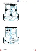
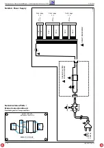
Schaltpläne und Druckplattenabbildungen / Circuit Diagrams and Layout of PCBs

RCD 2000

Schaltpläne und Druckplattenabbildungen / Circuit Diagrams and Layout of PCBs

RCD 2000

GRUNDIG Service

GRUNDIG Service

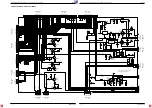
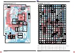
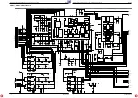
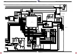
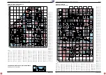
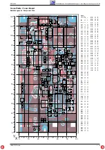
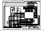
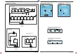
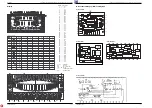
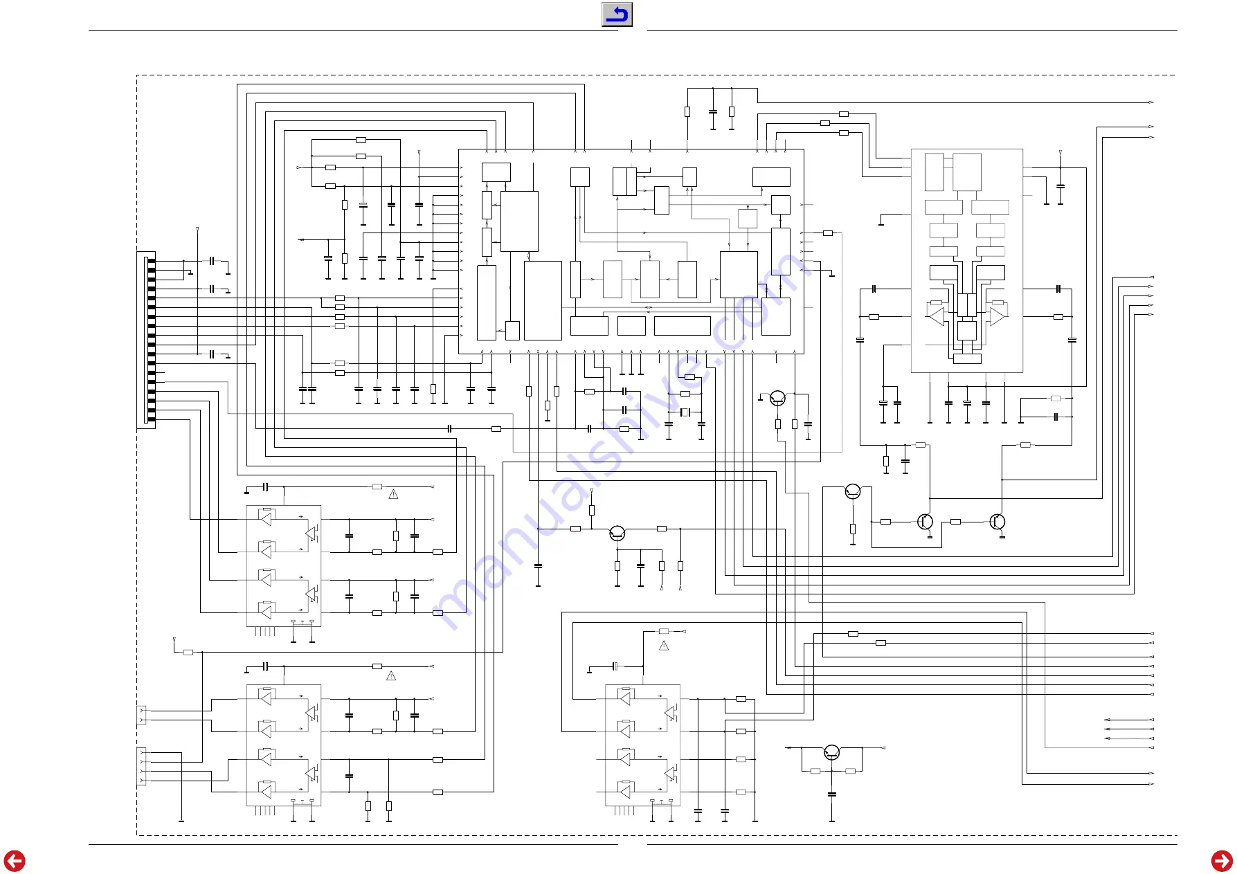
CD-Servo-Platte / CD Servo Board

3 - 8

3 - 9

1

2

3

4

5

6

7

8

9

10

11

12

13

14

15

16

1

2

3

4

5

6

7

8

9

10

11

12

13

14

15

16

17

18

19

20

21

22

23

24

25

26

27

28

29

30

31

32

33

34

35

36

37

38

39

40

41

42

43

44

45

46

47

48

49

50

51

52

53

54

55

56

57

58

59

60

61

62

63

64

1

2

3

4

5

6

7

8

9

10

11

12

13

14

15

16

17

18

1

2

3

4

5

6

7

8

9

10

11

12

13

14

15

16

1

2

3

4

5

6

7

8

9

10

11

12

13

14

15

16

1

2

3

4

1

2

3

4

5

6

7

8

9

10

11

12

13

14

15

16

1

2

C1654

C1653

R1655

IC1603

IC1601

C1655

C1652

P1601

C1651

C1656

R1656

R1651

C1646

C1643

C1644

C1645

R1645

R1644

R1643

C1626

C1623

C1624

C1621

R1625

R1622

R1626

R1624

R1623

R1621

C1627

R1627

C1662

R1662

C1660

R1661

R1669

R1668

R1667

R1671

IC1602

R1603

C1618

R1612

R1613

R1611

R1617

R1615

R1616

R1614

C161

1

C1615

C1617

IC1604

R1648

R1649

C1649

C1647

C1648

R1618

Q1601

C1642

C1641

R1641

R1642

C1663

R1663

R1639

R1638

C1636

R1636

C1632

R1633

T1601

R1632

R1634

R1635

R1631

T1604

C1601

R1601

R1602

P1603

IC1605

C1708

R1607

R1608

R1604

R1605

C1688

C1681

C1683

C1682

R1682

R1683

C1686

C1685

C1684

C1689

C1690

C1687

R1676

C1675

C1676

C1671

R1637

R1665

R1664

R1666

R1672

R1659

R1658

T1603

T1602

R1679

R1678

R1657

R1660

C1658

C1657

C1701

C1702

R1701

R1702

C1704

C1703

R1708

R1706

R1707

C1650

T1605

P1602

I-i

I-i

I+i

I+i

OUT-

OUT-

OUT+

OUT+

VP

IN-

IN-

IN+

IN+

NC NC NC NC NC

+

+

-

-

NC

Processor

Audio

Detect

Peak

Demodulator

EFM

SRAM

Processor

Subcode

RAM

Addresser

RCK

SUB

SFSY

SBSY

T

iming

Interface

Microcontroller

Decoder

ST

A

TUS

V5

V4

V3

V2

V1

Interface

V

ersatile Pins

Kill

Kill

/RESET

CL4

CL1

1

CL16

CROUT

CRIN

SELPLL

TEST3

TEST2

TEST1

Test

Digital PLL

Frontend

Iref

ISLICE

HFREF

HFIN

Interface

Microcontroller

SILD

RAB

SDA

SCL

V

ref

Generator

VRH

ADC

R2

R1

VRL

D1

D2

D3

D4

IrefT

Ctrl. Function

Part

Control

Pre-Processing

stages

Output

Control

Motor

Corrector

Error

Flags

Interface

EBU

Interface

Data

Serial

EF

D

ATA

WCLK

SCLK

DOBM

C2F

AIL

CFLG

MOT

O2

MOT

O1

LDON

SL

FO

RA

VDDDc3

VDDDp2

VDDDp1

VSSD4

VSSD3

VSSD2

VSSD1

VDDA2

VDDA1

VSSA3

VSSA2

VSSA1

+

+

put

out

sw

sw

put

out

left

rgt

curr.sinks

calibr.

curr.sources

curr.sources

16(4Bit) cal.

16(4Bit) cal.

16(4Bit)

VSSA

VDDA

VDDO

VSSO

Ref. Source

FILTCL

VOL

VOR

FILTCR

Vref

+

+

-

-

NC

VSSD

VDDD

Data Encoder

Data Encoder

interpolator

linear

halfband

7th order

FIR Filter

Noise Shaper

Noise Shaper

2nd order

2nd order

(Sample and hold)

(Sample and hold)

6 * oversampling

6 * oversampling

Test

Timing

and

Ctrl.

BCK

WS

DATA

+

I-i

I-i

I+i

I+i

OUT-

OUT-

OUT+

OUT+

VP

IN-

IN-

IN+

IN+

NC NC NC NC NC

+

+

-

-

+

I-i

I-i

I+i

I+i

OUT-

OUT-

OUT+

OUT+

VP

IN-

IN-

IN+

IN+

NC NC NC NC NC

+

+

-

-

+

+

+

+

+

+

+

220p/5%/16V

220p/5%/16V

10k

TDA7073A/AT

SAA7378GP

220p/5%/16V

220p/5%/16V

220p/5%/16V

220p/5%/16V

10k

270k

1n/5%/16V

47p/5%/16V

22n/5%/16V

100n/5%/16V

1k

22k

150k

560p

1.8n

5.6n

10n

1.2k

1.2k

6.8k

27k

6.8k

22k

47U/16V

3.3R

47U/16V

10R

10N/16V

C1661

10N/16V

47R

0R

R1698

10K

0R

0R

47R

TDA1549T

3.3R

47U/16V

100k

100k

56k

6.8k

1k

1k

1k

100n

220n

10n

TDA7073A/AT

1k

1k

47U/16V

100N/16V

100N/16V

10k

8.4672MHz

27p/NP0

27p/NP0

100K

330R

10n

220R

R1675

47k

R1697

100K

220R

220R

47p/5%/16V

220R

2.7p/0p25

10k

BC848B

T1699

BC848B

10k

100R

10k

10k

BC848B

10n

C1608

2.2U/16V

C1607

2.2U/16V

100R

220R

TDA7073A/AT

47U/16V

6.2k

6.2k

100k

100k

22n

22n

1n/5%/16V

1n/5%/16V

470R

470R

22U/16V

4.7U/16V

4.7U/16V

22n

100U/16V

22n

47k

1.5n/5%/16V

220p/16V

220R

10k

10k

22k

100R

10k

10k

BC848B

BC858B

1k

1k

10k

10k

1.5N/5%/16V

560p/5%/16V

4.7U/16V

4.7U/16V

100R

33R

10N/16V

10N/16V

3.3R

1k

1k

22N

BC848B

T

O

  PICKUP

 UNIT

LO

LD

HG

LS

T

O

  PICKUP

 UNIT

RFE

FOCUS

LDON

(D5)

(D3)

UREF

UREF

UREF

UREF

HOME

TT+

SL+

SLIDE

RADIAL

TU

TURNTABLE-

R+

R-

F+

F-

SL-

TT-

SBSY

CD-RESET

CL4

SFSY

SUB

RCK

SICL

SILD

VDD

VDD

VDD

VDD

VDD

VDD

TRAY-

TRAY+

+5V-CD

+CD

+SERVO

SR

+5V-CD

+5V-CD

CD-MUTE

(D1)

(D4)

DTA

(D2)

GNDA

GNDA

GNDA

GNDA

GNDA

GNDA

GNDA

1.5n/5%/16V

GNDA

GNDA

GNDA

GNDA

+SERVO

+SERVO

+CD

+5V-CD

TRAYMOT-

EBU

ANOUT-R

ANOUT-L

+5V-CD

Summary of Contents for RCD 2000

Page 1: ...Uhr 0180 52318 41 0180 52318 49 0180 52318 48 0180 52318 42 0180 52318 43 0180 52318 44 0180 52318 45 0180 52318 51 0180 52318 99 Mo Fr 8 00 18 00 Uhr 0180 52318 40 0180 52318 50 Telefon Fax Technik E...

Page 2: ...Inhaltsverzeichnis Seite Allgemeiner Teil 1 2 1 13 Messger te Messmittel 1 2 Servicehinweis 1 3 Technische Daten 1 3 Ausbauhinweise 1 4 Bedienheinweise 1 7 Abgleichvorschriften 2 1 2 2 Schaltpl ne und...

Page 3: ...rtion IEC wtd 0 01 Stereo crosstalk 20Hz 20kHz 85dB Intermodulation 0 1 Dynamic range 100dB Signal to noise ratio wtd 100dB Phase linearity 0 5 Fixed output 2 0V Power supply Mains voltage 230V Mains...

Page 4: ...erbinder nach Bedarf ffnen 3 NF Platte b ausbauen Boden entfernen Pkt 1 3 Schrauben B Fig 2 und 4 Schrauben F Fig 3 herausschrau ben und NF Platte herausnehmen Kabelbinder und Steckverbinder nach Beda...

Page 5: ...nter den 4 Tasten Q befinden sich Federn Kabelbinder und Steckverbinder nach Bedarf ffnen 13 Linke Tasten ausbauen Tastenplatte links ausbauen Pkt 11 4 Schrauben R herausschrauben und Tasten herausneh...

Page 6: ...screwsEand take out the CD bottom plate Fig 11 Fig 10 Fig 11 Fig 9 Z E A D Z C B U Y S P k Q P S R O j R 14 Rechte Tasten ausbauen Tastenplatte rechts ausbauen Pkt 12 4 Schrauben S herausschrauben und...

Page 7: ...uner Betrieb Programmpl tze MEMO MEMO speichert Einstellungen Mit Taste OK best tigen Sie die gew hlte Funktion Hinweis Um die Batterien zu schonen schaltet die Anzeige der Fernbedienung nach kurzer Z...

Page 8: ...__________ 4 Einstellung HORIZONTAL mit 4 an der HiFi Anlage best tigen Anzeige an der HiFi Anlage INSTALL 5 Die beiliegenden drei Batterien in das Batteriefach der Fernbedienung einle gen dabei Polun...

Page 9: ...fangskanal der HiFi Anlage und der Lautsprecher ver ndern Sollte es bei der Ton bertragung zu St rungen kommen dies kann der Fall sein wenn ein anderes Ger t auf der gleichen Sendefrequenz sendet kann...

Page 10: ...Besonderheiten des Mehrraum Betriebes Sie k nnen bis zu f nf zus tzliche Lautsprecherpaare auf mehrere R ume ver teilt mit der HiFi Anlage betreiben Damit Sie nicht immer die Fernbedienung von Raum zu...

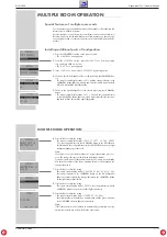
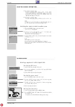
Page 11: ...nschalten siehe n chstes Kapitel MEHRRAUM BETRIEB________________________________________________________________ INSTALL 1 SELECT LEFT LS AND PRESS OK INSTALL 1 READY INSTALL 1 CONFIRM RIGHT LS WITH...

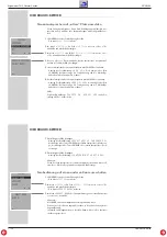
Page 12: ...lfe Erscheint die Meldung ALL SETS ON RCD LS1 LS2 nicht Ein stellung ab Pkt 1 wiederholen REPLACE SPEAKERS SELECT ROOM 1 BACK INSTALL SPEAKERS REPLACE SPEAKERS RC BACK p o MEHRRAUM BETRIEB____________...

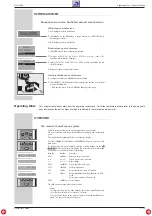
Page 13: ...NNEL INSTALL OVERVIEW__________________________________________________________________________________ The remote control menu system Your HiFi system s remote control unit is equipped with a menu sy...

Page 14: ...OOM TONE CONTROL SOUND MODE BACK p o CONNECTION AND PREPARATION_______________________________________ Connecting and installing the loudspeakers The HiFi transmits audio signals by radio to the louds...

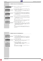
Page 15: ...rm the setting The remote control display reads SELECT LEFT LS AND PRESS OK the orange indicator in the POWER button on the left loud speaker flashes and the orange indicator in the POWER button on th...

Page 16: ...iFi to switch the system to Vertical operating mode The HiFi display reads VERTIKAL 4 Confirm the setting by pressing 4 on the HiFi 5 Press the OPEN CLOSE button on the HiFi to open the CD compartment...

Page 17: ...TALL 1 ALL SPEAKERS ON LS1 INSTALL 1 ALL SPEAKERS ON LS1 LS2 6 Press OK to confirm the setting The remote control display reads SELECT LEFT LS AND PRESS OK the orange indicator in the POWER button on...

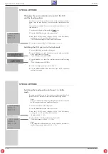
Page 18: ...rect The second remote control is now ready for operation INSTALL 1 SPEAKERS REPLACE SPEAKERS RC BACK p o INSTALL 1 INSERT BATTERIES IN THE NEW RC MULTIPLE ROOM OPERATION______________________________...

Page 19: ...K to return to the main menu You can only select rooms in which loudspeakers are configured Changes to the volume and tone for individual rooms are saved in the louds peakers themselves CONTROL SELECT...

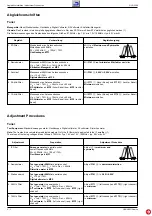
Page 20: ...er Kanal bzw MP3 rechter Kanal Messsender an Antennenbuchse UHF 1mV 75 fmod 19kHz Hub 40kHz NF Voltmeter an MP2 linker Kanal bzw MP3 rechter Kanal Adjustment Procedures Tuner Test Equipment Standard s...

Page 21: ...ayout BeimAustauscheinesderZF Filter F101 F102 achtenSiedarauf dassnur Filter mit gleicher Kennfarbe best ckt sind When replacing one of the ceramic resonators F101 F102 take care that the colour code...

Page 22: ...ldungen Circuit Diagrams and Layout of PCBs Verdrahtungsplan Wiring Diagram 1 5 P2010 5VR KEY0 STDBY GNDR TASTEN PLATTE RECHTS SWITCH BOARD RIGHT P210 P200 1 P700 P220 P240 P230 P280 P201 P930 TUNER I...

Page 23: ...48 47 44 43 42 41 40 39 38 37 36 35 34 33 32 31 30 28 27 25 24 23 22 21 20 19 18 17 16 15 14 13 12 11 10 9 8 7 6 3 2 1 5 1 P3008 12 1 P3014 2 1 P3013 P3001 P3020 12 1 P3007 4 1 P3005 P3011 11 1 P3004...

Page 24: ...8 9 10 11 12 P3009 1 2 3 P3011 1 2 3 4 5 REM ON REM ON WAKEUP SCLK SCLK 5V 5V 5V 5V 5V 5V 5V 5V 5V 5V SIN SIN LED1 LED1 SOUT SOUT LDC LDC TX PD TX PD SRDY SRDY RDC RDC TXD TXD 2200U 25V C925 12V 12V 1...

Page 25: ...F BOARD NF BOARD TX RIGHT SWITCH FRONT SWITCH HF REMOTE TRAFO TRAFO TRAFO SWITCH LEFT TUN SUP FM TUNER SERVO SERVO MOTOR CD CD Control RCD2000 130 120 110 100 90 80 70 60 50 40 30 20 10 0 190 180 170...

Page 26: ...VRL D1 D2 D3 D4 IrefT Ctrl Function Part Control Pre Processing stages Output Control Motor Corrector Error Flags Interface EBU Interface Data Serial EF DATA WCLK SCLK DOBM C2FAIL CFLG MOTO2 MOTO1 LDO...

Page 27: ...P20 SI30 P36 _SCK31 P35 SO31 P34 SI31 P33 P32 P31 P30 VSS0 VDD0 P57 A15 P56 A14 P55 A13 P54 A12 P53 A11 P52 A10 P51 A9 P50 A8 3 2 1 GND OUT IN 22N 1N4001 22k 47U 74HCT573M 10k 1k 4 7k LL4148 LL4148 5...

Page 28: ...3 24 R1664 99 18 R1665 101 17 R1666 101 21 R1667 27 10 R1668 25 10 R1669 29 10 R1671 10 16 R1672 10 15 R1675 95 8 R1676 95 11 R1678 98 5 R1679 97 17 R1682 91 8 R1683 91 13 R1691 76 37 R1692 76 38 R169...

Page 29: ...10K R305 10K R304 47p C303 27K R303 47p C302 27K R302 100n C952 100n 63V C951 P200 1 2 3 100N C713 4K7 R716 6 5 4 3 2 1 P930 2K2 R267 2K2 R268 BC848B T262 BC848B T261 2K2 R301 2K2 R300 BC848B T293 BC8...

Page 30: ...148 6K2 R149 10K R143 1N C144 1U 50V C147 BC848B T151 100N 63V C111 100N C112 ADJUST LM317 OUT IN IC110 470 16V C117 100N C116 6K2 R150 ST101 OPT C180 ST171 100N C103 10U 16V C113 100N C100 LL4148 D11...

Page 31: ...10 73 R128 10 75 R129 10 77 R132 10 69 C184 C135 L101 C103 P142 F171 IC180 T102 D161 C100 D S T131 C133 F101 2 3 1 IC110 F141 FE100 C113 R166 Q120 R148 C117 C149 R101 R100 R102 R103 C101 R104 R106 C12...

Page 32: ...12 R334 R333 D300 X301 02 05 2000 59472 308 00 05 4B DISPLAY PCB RCD2000 120 110 100 90 80 70 60 50 40 30 20 10 0 60 50 40 30 20 10 0 X Y I C 3 0 0 JST 1 JST 1 Bauteil Component X Y C300 34 20 C301 35...

Page 33: ...9 P14 FLD20 P15 FLD21 P16 FLD22 FLD23 P17 P30 FLD24 P32 FLD26 P31 FLD25 P33 FLD27 P34 FLD28 P35 FLD29 P36 FLD30 P37 FLD31 P80 FLD32 P81 FLD33 P82 FLD34 P83 FLD35 FLD39 P87 PWM0 Vee P84 FLD36 FLD37 P85...

Page 34: ...GNDL GREEN RED ON OFF STDBY 17 09 99 PAUSE STOP to P3009 CD CONTROL BOARD to P3010 CD CONTROL BOARD to P3008 CD CONTROL BOARD LED NEXT PLAY PREV KEYLIGHT Tastenplatte links SWITCH BOARD LEFT Tastenpl...

Page 35: ...omponent Side Tastenplatte rechts Switch Board right L tseite Solder Side 1 5 P2010 D2014 D2013 D2012 D2011 D2010 K2018 K2012 K2011 K2015 K2017 K2016 K2014 K2013 5VR KEY0 STDBY GNDR MUTE UP DOWN NEXT...

Page 36: ...10 CD CONTROL to P900 CD CONTROL to P920 CD CONTROL SI01 P03 F01 MAINS 2 1 1 2 3 4 1 2 BL PTR2 BN PTR1 T315mA L 102 C Netz Anschluss Platte MAINS CON BOARD 16 5V 16 5V 1 9V 1 9V 35 7V 9 8V MAINS SWITC...

Page 37: ...32 2G 33 3G 34 4G 35 5G 36 6G 37 7G 38 8G 39 9G 40 10G 41 11G 42 12G 43 13G 44 14G 45 N P 46 N P 47 F2 48 F2 49 F2 F1 F2 Filament N P No Pin N C No Connection 1G 14G Grid I C Internal Connection G d D...

Page 38: ...ded Views and Spare Parts List RCD 2000 Explosionszeichnungen und Ersatzteilliste Exploded Views and Spare Parts List RCD 2000 GRUNDIG Service GRUNDIG Service 4 1 4 2 Explosionszeichnungen und Ersatzt...

Page 39: ...RCD 2000 Explosionszeichnungen und Ersatzteilliste Exploded Views and Spare Parts List GRUNDIG Service 4 3 2 44 41 42 40 30 31 32 35 38 33 34 20 21 22 22 25 26 27 28 600 25 36 46 43 39 37...

Page 40: ...RING CD CONTROL 0026 000 2 55401 404 0000 DRUCKFEDER CD EJECT PRESSURE SPRING CD EJECT 0027 000 2 55401 232 0100 KNOPF CD EJECT KNOB CD EJECT 0028 000 2 55401 231 0100 KNOPF CD CONTROL KNOB CD CONTROL...

Page 41: ...C 00270 83058 473 1300 SMD IC TDA7313D 013TR IC 00290 83057 598 3300 SMD IC LM833D IC 00300 83057 524 5000 SMD IC M38B59EFFP MIT IC 00340 83059 600 2200 SMD IC X24C04S8 2 7C7000 IC 00360 83057 598 330...

Page 42: ...800 SMD TRANS BC848B BC847B T 00702 83010 038 5800 SMD TRANS BC858B BC857B T 00920 83010 048 4800 SMD TRANS BC848B BC847B T 01601 83010 048 4800 SMD TRANS BC848B BC847B T 01602 83010 038 5800 SMD TRAN...

Reviews: