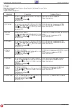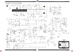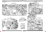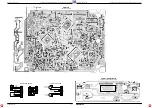
Allgemeiner Teil / General Section
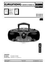
RR 3200 CD / RR 3500 CD
1 - 6
GRUNDIG Service
Disassembly Instructions
General Notes on the Mechanical Section.
All the screws which are screwed into plastic parts should be turned
counter clockwise first until you notice that the screw has found the
first thread. Then tighten the screw. This preventive measure en-
sures that no new threads are cut into the plastic material thus
deteriorating the good fit of the screw.
If screws secured with lacquer have to be loosened, they must be
resecured in the same manner when the repair is completed.
Magnetic tools shall not be brought near the magnetic heads.
Each time repair work has been carried out on the cassette drive
mechanism, clean the heads, the capstans and the rubber pinch
rollers with spirit or cleaning benzine.
Ausbauhinweise
Allgemeines zum mechanischen Teil.
Alle Schrauben, die in Kunststoff eingedreht werden, sollten zuerst
soweit gegen den Uhrzeigersinn gedreht werden, bis Sie merken, die
Schraube hat den Gewindeanfang gefunden. Erst dann ist die
Schraube festzudrehen. Dadurch wird vermieden, daß ein neues
Gewinde in den Kunststoff geschnitten wird und der Halt der Schrau-
be verlorengeht.
Ist es erforderlich, lackgesicherte Schrauben zu lösen, müssen diese
nach Abschluß der Reparatur wieder verlackt werden.
Magnetische Werkzeuge dürfen nicht in die Nähe der Magnetköpfe
gebracht werden.
Nach jeder Reparatur am Cassettenlaufwerk sind die Köpfe, die
Tonwellen und die Andruckrollen mit Spiritus oder Reinigungsbenzin
zu reinigen.
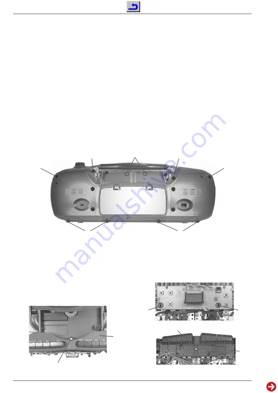
Fig. 4
Fig. 2
Fig. 3
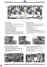
2. Cass.-Laufwerk ausbauen
- Gehäusevorderteil abnehmen (siehe Pkt. 1).
- 2 Halter
D
(Fig. 3) ausrasten und Display-Platte abnehmen.
- Schraube
E
(Fig. 4) herausdrehen und Plattenhalter
F
abnehmen.
- 7 Schrauben
G
(Fig. 5) herausdrehen.
- Tastenblende
H
(Fig. 2) abnehmen.
- Laufwerk herausnehmen.
- Eventuell Kabelbinder lösen.
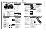
2. Dismantling the Cassette Drive Mechanism
- Remove the cabinet front (see para 1).
- Disengage the 2 lugs
D
(Fig. 3) and remove the display board.
- Undo the screw
E
(Fig. 4) and remove the panel holder
F
.
- Undo 7 screws
G
(Fig. 5).
- Remove the button panel
H
(Fig. 2).
- Take out the cassette drive mechanism.
- Eventually loosen the cable ties.
C
H
D
D
F
E
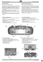
1. Gehäusevorderteil abnehmen
- 2 Schrauben
A
(lang) und 6 Schrauben
B
(kurz) herausdrehen
(Fig. 1).
- Schraube
C
im CD-Fach (Fig. 2) herausdrehen.
- Beide Cassettenfachdeckel durch Drücken der Tasten
9 /
(Stop/
Eject) öffnen.
- Gehäusevorderteil nach vorne abnehmen.
- Lautsprecherstecker abziehen.
- Mikrofon aus der Halterung (Gehäusevorderteil) ziehen.
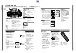
1. Removing the Cabinet Front
- Undo 2 screws
A
(long) and 6 screws
B
(short) (Fig. 1).
- Undo the screw
C
in the CD compartment (Fig. 2).
- Open both cassette compartment lids by pressing the buttons
9 /
(Stop/Eject).
- Remove the front of the cabinet towards the front.
- Disconnect the speaker plug.
- Take the microphone out of its holder (cabinet front).
Fig. 1
B
A
A
L
B
B
B
Display Board

