background image

RR 3200 CD / RR 3500 CD

Allgemeiner Teil / General Section

GRUNDIG Service

1 - 7

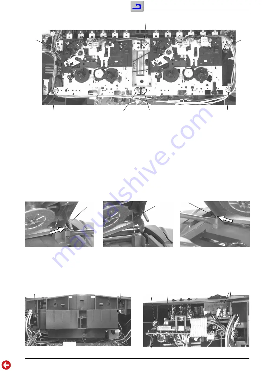
Fig. 9

G

G

G

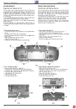
4. Leiterplatten (Power, EQ/Volume) ausbauen
- Gehäusevorderteil abnehmen (siehe Pkt. 1).
- 2 Halter 

D

 (Fig. 3) ausrasten und Display-Platte abnehmen.

- Schraube 

E

 herausdrehen und Plattenhalter 

F

 abnehmen (Fig. 4).

- 3 Schrauben 

O

 (Fig. 10) herausdrehen.

- Leiterplatten (Power, EQ/Volume) vorsichtig herausnehmen.
- Eventuell Kabelbinder lösen.

M

G

Fig. 5

G

G

I

J

K

Fig. 6

Fig. 7

Fig. 8

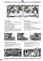
3. CD-Einheit ausbauen
- CD-Fachdeckel öffnen.
- Rechtes Deckelscharnier 

I

 mit einem Schraubendreher nach

außen drücken (Fig. 6) und Deckel ausrasten (Fig. 7), achten Sie
dabei auf die Deckelfeder 

J

.

- Linkes Deckelscharnier 

K

 mit einem Schraubendreher nach außen

drücken (Fig. 8) und Deckel abnehmen.

- Cass.-Laufwerk ausbauen (siehe Pkt. 2).
- 2 Schrauben 

L

 (Fig. 1) herausdrehen.

- 2 Schrauben 

M

 (Fig. 9) herausdrehen.

- CD-Einheit nach vorne herausnehmen.
- Bei Bedarf Steckverbindungen abziehen.
Bei Ausbau der CD-Lasereinheit muß vor Abziehen der Steckver-

bindungen eine Schutzlötstelle 

N

 auf der Leiterplatte der Laser-

einheit angebracht werden, um eine Zerstörung der Laserdiode
durch statische Aufladung zu vermeiden (siehe Seite 1 - 2 "Service-
hinweise").

3. Removing the CD Unit
- Open CD compartment lid.
- Press the right hinge of the lid 

I

 outwards with a screwdriver (Fig. 6)

and disengage the lid (Fig. 7); take car of the lid spring 

J

.

- Press the left hinge of the lid 

K

 outwards with a screwdriver (Fig. 8)

and take off the lid.

- Remove the cass. mechanism (see para 2).
- Undo 2 screws 

L

 (Fig. 1).

- Undo 2 screws 

M

 (Fig. 9).

- Remove the CD unit towards the front.
- Disconnect the plug-in connections if necessary.
When removing the Laser pick-up, the pick-up PCB must be provided

with a protective soldered joint 

N

 before unplugging the connec-

tors to avoid damage to the Laser diode by static charges (see
page 1 - 2 "Service Hints").

G

M

O

4. Removing the Power and EQ/Volume Circuit Board
- Remove the cabinet front (see para 1).
- Disengage the 2 lugs 

D

 (Fig. 3) and remove the display board.

- Undo the screw 

E

 and remove the panel holder 

F

 (Fig. 4).

- Undo 3 screws 

O

 (Fig. 10).

- Take out the power and EQ/volume circuit board carefully.
- Eventually loosen the cable ties.

O

EQ/Volume Board

Power Board

Fig. 10

Summary of Contents for RR 3200 CD

Page 1: ...ice Manuals for the Complete Service RR 3200 CD 75 3124 1051 G DG 6651 RR 3500 CD 75 3125 1051 G DG 6751 Remote Control 75954 046 34 nur only RR 3500 CD SERVICE MANUAL RR 3200 CD RR 3500 CD STOP PREV...

Page 2: ...bauhinweise 1 6 Einstellvorschriften 2 1 2 3 Schaltpl ne und Platinenabbildungen 3 1 3 16 Verdrahtungsplan 3 1 Schaltpl ne Tuner und NF Teil RR 3500 CD 3 3 Lautst rkeregelung und IR Empf nger RR 3500...

Page 3: ...14kHz S N ratio weighted 62dB Servicehinweise Cassettenteil berpr fenSievorBeginnderService Arbeiten ob die Magnetk pfe die Tonwellen und die Gummiandruckrollen frei von Bandabrieb sind Zum Reinigen d...

Page 4: ...REVIOUS oder NEXT dr cken bis die Nummer des gew nschten Titels im Anzeigefeld erscheint Die Wiedergabe wird unterbrochen und kurz danach beginnt die Wiedergabe des gew hlten St cks Beginnen mit einem...

Page 5: ...ways store it in its box after use with the label facing up To remove dust and dirt breathe on the CD and wipe it with a soft lint free cloth in a straight line from the center towards the edge Cleani...

Page 6: ...d rfen nicht in die N he der Magnetk pfe gebracht werden Nach jeder Reparatur am Cassettenlaufwerk sind die K pfe die Tonwellen und die Andruckrollen mit Spiritus oder Reinigungsbenzin zu reinigen Fi...

Page 7: ...Schutzl tstelle N auf der Leiterplatte der Laser einheit angebracht werden um eine Zerst rung der Laserdiode durch statische Aufladung zu vermeiden siehe Seite 1 2 Service hinweise 3 Removing the CD U...

Page 8: ...tcassette 456 Sach Nr 35079 014 00 Abgleichlageplan siehe Seite 2 3 Frequenzz hler an Kopfh rerbuchse Normal Speed Testcassette 449 in Deck A einlegen 3150Hz abspielen High Speed Leercassette in Deck...

Page 9: ...wechselseitig wiederholen Mit VR101 152kHz 100Hz einstellen Wobbelsender 468kHz ber 10nF an Me punkt A Oszilloskop an Me punkt 1 Bandschalter MW Drehkoanschlag MW fu 526 5kHz fo 1606 5kHz Me sendersi...

Page 10: ...T104 T103 T101 L105 T102 TC2 TC3 TC1 TC4 D101 R103 L101 MW L102 LW 1 D B A C FM LW MW CD Best ckungsseite Component side CN17 CN16 CN18 CN3 CN2 CN1 IC105 IC101 IC102 CNS108 TP TRACKING TP D GND TP A...

Page 11: ...heheadphonesocket Normal Speed Insert the test cassette 449 in Deck A Play 3150Hz High Speed Insert a recordable cassette in Deck B Deck B Record Pause Function High Speed Dubbing Insert the test cass...

Page 12: ...to limit stop MW fu 526 5kHz fo 1606 5kHz Couple in a standard signal to ferrite aerial via a loop aerial B fmod 1kHz m 30 Ua as low as possible Oscilloscope to testpoint 1 Band switch MW MW 600kHz M...

Page 13: ...shielding white orange red brown red shielding white CNP 106 green yellow red red black black red yellow orange 9 pin flat cable CNS 101 4 yellow yellow red red black black red white orange yellow re...

Page 14: ...D C A TP5 TP6 S NORM SPEED HIGH SPEED 0 2 6 5V 7 1V 0V 0 7V 1 2V 1 3V 1 3V 3 9V 4 8V 1 4V 2V 1 2V 1 2V 0V REC 0 5V 0 2 12V 6 3V 6 3V 12V 0 0 0V To CNS107 Page 3 12 To CNS108 Page 3 12 To CNP102 Displa...

Page 15: ...6V 0 6V 5 2V 0V 5 4V 1 7V 4 4V 4 4V 2 8V 2 8V 5 5V 3 3V 2 8V 2 8V 2 8V 5 1V 2 8V 2 8V 5 1V 2 8V VOLUME CONTROL REMOTE CONTROL Lautst rkeregelung und IR Empf nger Volume Control and Remote Control RR 3...

Page 16: ...V FM 2 7 2 6 2 1 0 5 0 0 0 1 0 4 5 0 1 0 0 5 1 2 4 1 0 0 7 V FM 0 4 0 4 1 0 1 0 0 0 7 1 4 0 6 1 4 0 7 0 0 0 1 4 0 7 PIN 17 18 19 20 21 22 23 24 25 26 27 28 29 30 31 32 PIN 1 2 3 4 5 6 7 8 9 10 11 12...

Page 17: ...vice GRUNDIG Service GRUNDIG Service GRUNDIG Service 3 10 Power Board RR 3200 CD Leiterplatten PCBs Best ckungsseite Component Side EQ Volume Board RR 3200 CD Tuner Board RR 3200 CD RR 3500 CD Cass Au...

Page 18: ...0 4 8 5 5 5 5 0 5 5 V 0 0 0 2 0 1 0 1 0 1 0 1 0 0 5 0 0 5 4 5 4 2 5 2 5 2 5 2 5 2 5 2 5 V 2 5 2 5 2 5 2 5 2 5 2 5 2 5 2 5 2 5 2 5 2 5 2 5 2 5 2 5 2 5 VOLTAGES IC105 LC708031A IC105 LC708031A SYSTEM C...

Page 19: ...or Sled Motor CD MOTOR BOARD Innen Schalter Inner Switch SP SP L SW L SW SL SL 1 2 3 4 5 6 LD GND MD VR FCS TRK TRK FCS FOCUS TRACK LASER HEAD BOARD 1 2 5 4 3 S 1 2 3 4 5 6 7 8 Control Display Board B...

Page 20: ...ROL AND TEST LEVEL SHIFT DAC R STRING DAC LEVEL SHIFT DAC R STRING DAC 5 8 9 CH1 OUT V REF H V REF L CH2 OUT TST OUT DATA R DATA L LRCK BCLK SYSCLK FSEL MODE2 MODE1 CH1 LATCH CH2 LATCH SIPO REGISTER P...

Page 21: ...nung RR 3200 CD Exploded View RR 3200 CD 105 25 89 120 120 119 118 117 116 101 102 103 114 113 115 104 106 107 108 109 110 111 112 89 59 58 61 60 62 17 16 15 14 100 88 99 98 97 93 96 95 94 92 91 90 83...

Page 22: ...TC38 063 03 E P SOCKET TC38 063 03 0128 000 75954 021 06 KONDENSATORMIKROFON WM 54 BY COND MICROPHONE WM 54 BY 72010 747 90 BEDIENUNGSANLEITUNG INSTRUCTION MANUAL 72010 751 80 SERVICE MANUAL D GB SERV...

Page 23: ...25 89 123 121 120 119 118 117 116 101 102 103 114 113 115 104 105 106 107 108 109 110 111 112 89 59 58 61 60 62 17 16 15 14 100 88 99 98 97 93 96 95 94 92 91 90 83 84 82 81 80 78 87 86 85 76 77 73 74...

Page 24: ...1861 COIL T 103 75954 048 02 SPULE AM OSC COIL T 104 75954 048 03 SPULE LW OSC GRUEN COIL TC 101 8699 998 116 TR 53 4 5 20PF TC 102 8699 998 116 TR 53 4 5 20PF VC 75954 046 33 DREHKO PVC FAT 16B2C VR...

Reviews: