RR 430 CD
Allgemeiner Teil / General Section
GRUNDIG Service
1 - 5
Ausbauhinweise
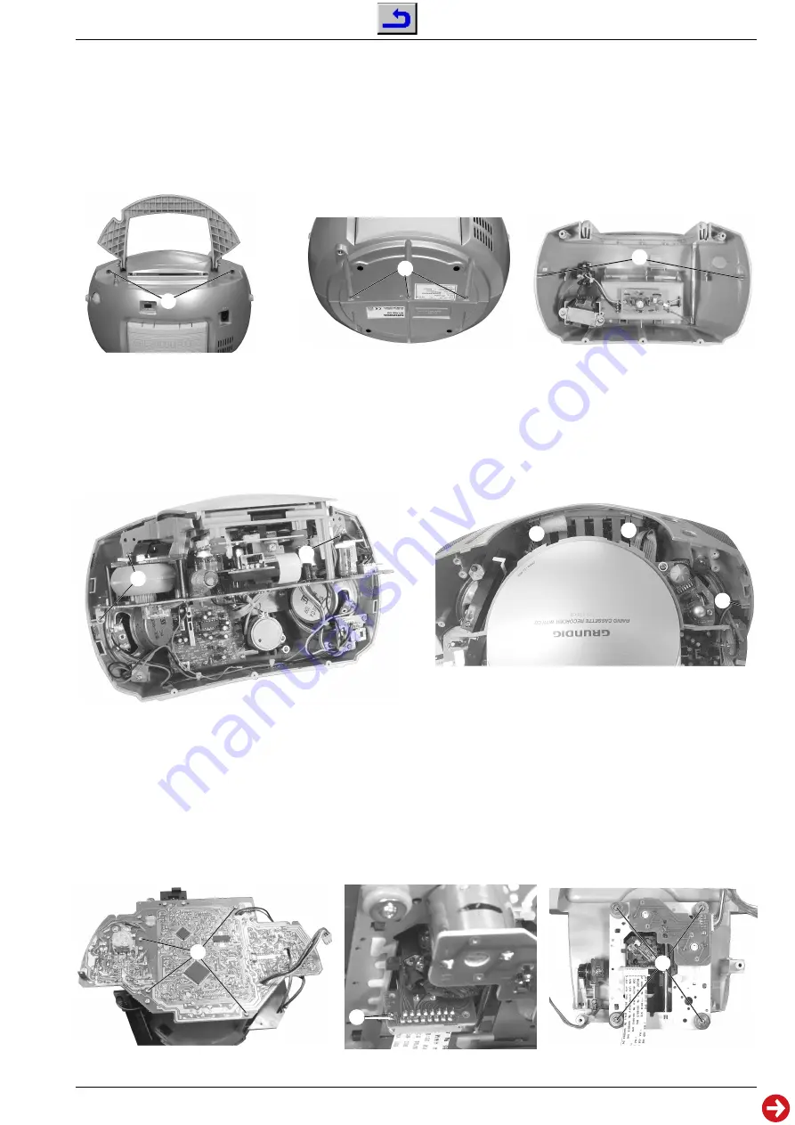
1. Öffnen des Gehäuses
- Knöpfe von Band- und Function-Schaltern abziehen.
- 2 Schrauben
A
(Fig. 1) und 3 Schrauben
B
(Fig. 2) herausschrauben.
- Gehäuserückteil vorsichtig nach hinten abnehmen, dabei die An-
tennenleitung und die Leitungen für die Spannungsversorgung abzie-
hen.
- Beim Zusammenbau darauf achten, daß die Hauptplatte in den
Führungen
C
(Fig. 3) liegt.
Disassembly Instructions
1. Opening the Cabinet
- Pull off the knobs of the band and function switches.
- Undo 2 screws
A
(Fig. 1) and 3 screws
B
(Fig. 2).
- Carefully remove the rear of the cabinet and disconnect the antenna
wire and the wires of the power supply.
- When reassembling insert main PCB into its guides
C
(Fig. 3).
Fig. 1
2. Hauptplatte mit CD-Mechanik
- 3 Schrauben
D
(Fig. 4) herausschrauben.
Einbaureihenfolge:
- Bedienknöpfe für USB und Volume in die Frontblende einführen.
- Hauptplatte in die Führung
E
(Fig. 5) einführen.
- CD-Gehäuse in die Führungen
F
(Fig. 5) einführen.
2. Main PCB together with CD Mechanics
- Undo 3 screws
D
(Fig. 4).
Reassembling:
- Insert the USB and Volume Buttons into the front cover.
- Insert the main PCB into guide
E
(Fig. 5).
- Insert the CD housing into the guides
F
(Fig. 5).
A
B
C
Fig. 2
Fig. 3
Fig. 4
D
Fig. 5
D
E
F
F
3. CD-Mechanik
- Hauptplatte mit CD-Mechanik ausbauen (Punkt 2).
- 4 Schrauben
G
(Fig. 6) herausschrauben.
- CD-Mechanik vorsichtig abnehmen. Vor Abziehen der Flexprint-
leitung Schutzlötstelle anbringen (
H
kurzschließen; Fig. 7).
4. CD-Laufwerk
- CD-Mechanik ausbauen (Punkt 3).
- 4 Schrauben
I
(Fig. 8) herausschrauben.
Fig. 6
G
Fig. 7
Fig. 8
H
I
3. CD Mechanics
- Remove the Main PCB together with the CD Mechanics (para 2).
- Undo 4 screws
G
(Fig. 6).
- Carefully remove the CD mechaniks. Attach a safety solder point
before disconnecting the flexprint (short circuit
H
; Fig. 7).
4. CD Mechanism
- Remove the CD Mechanics (para 3).
- Undo 4 screws
I
(Fig. 8).


