TVR 3710 FR, TVR 5100 FR, TVR 5500 FR
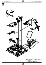
Platine mécanique / Drive Mechanism
GRUNDIG Service
5 - 7
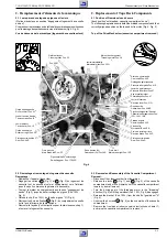
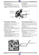
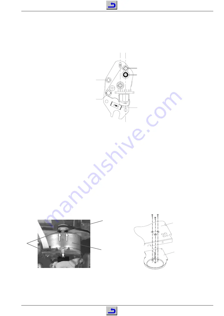
2.4 La tête son-synchro (Pos. 36)
– Retirer le ressort de fixation "A" (Fig. 14) et défaire le connecteur.
– Dévisser la vis de montage "B" et échanger la tête son-synchro.
– Pour le montage utiliser le nouveau ressort de fixation fourni avec la
tête.
Après remplacement de la tête son-synchro, tous les réglages indi-
qués aux points 3.1.2 et 3.2 doivent être effectués.
2.4 A/C Head (combi head, Pos. 36)
– Remove fixing spring "A" (Fig. 14) and unplug the connector.
– Undo the mounting screw "B" and replace the A/C (combi) head.
– Use the new fixing spring delivered with the replacement A/C head
for reassembly.
After the A/C head has been replaced, all adjustments described in
para 3.1.2 and para 3.2 have to be carried out.
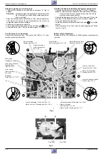
Fig. 15
Fig. 16
Vis de montage B
Mounting screw B
Réglage de l'angle d'inclinaison
Tilt setting screw
A
Réglage de la hauteur
Height setting screw
Réglage de l'azimut
Azimuth adjustment
screw
Fig. 14
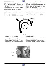
2.5 Moteur de chargement (Pos. 38)
– Enlever la courroie d'entraînement (Pos. 39) et retirer le câble du
moteur (Fig. 15).
– Pousser le support moteur (Pos. 40M) dans le sens de la flèche et
retirer le moteur de chargement (Pos. 38) de son support (Fig. 15).
Lors du montage,veiller à ce que le moteur soit bien enclenché dans
les supports avant et arrière.
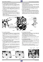
2.6 Le moteur cabestan (Pos. 127)
– Amener la mécanique en position "Eject".
– Retirer la courroie d'entraînement (Pos. 126).
– Débloquer et soulever vers le haut le C.I. capteurs situé au-dessus
du moteur cabestan.
– Retirer les 3 vis de fixation (Fig. 16) de la face supérieure et retirer
le moteur cabestan de la mécanique par le bas.
Le remontage s'effectue dans l'ordre inverse. Veiller à ce que l'axe de
cabestan soit exempt de graisse.
2.5 Threading Motor (Pos. 38)
– Remove the drive belt (Pos. 39, Fig. 15) and unplug the connector
from the threading motor.
– Press the motor support (Pos. 40M) in the direction of the arrow and
take the threading motor (Pos. 38) out of the motor support (Fig. 15).
When fitting the motor ensure that the threading motor locks into the
front and rear bearing.
2.6 Capstan Motor (Pos. 127)
– Set the tape deck to the "Eject" position.
– Remove the driving belt (pos.126).
– Release the sensor print covering the capstan motor and fold it up.
– Remove the three capstan motor fixing screws (Fig. 16) and with-
draw the capstan motor downward from the tape deck.
Reassembly is carried out in reverse order. Make sure that the capstan
is free of grease.
38
39
40M
Moteur cabestan
Capstanmotor
127
Châssis
Chassis
Summary of Contents for TVR 3710 FR
Page 16: ...Partie g n rale General Section TVR 3710 FR TVR 5100 FR TVR 5500 FR 1 16 GRUNDIG Service Notes...
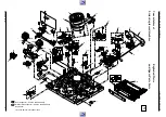
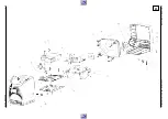
Page 91: ...TVR 3710 FR TVR 5100 FR TVR 5500 FR Vues clat es Exploded Views GRUNDIG Service E 3 3...
Page 92: ...Vues clat es Exploded Views TVR 3710 FR TVR 5100 FR TVR 5500 FR E 4 GRUNDIG Service 4...


