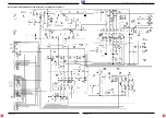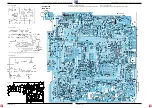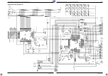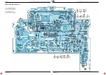
UMS 200
Abgleichvorschriften / Adjustment Procedures
GRUNDIG Service
2 - 4
Adjustment Procedures
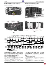
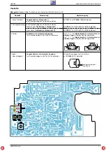
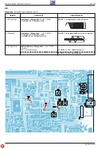
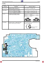
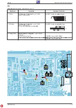
Tuner
Test equipment:
Sweep / Signal Generator, Oscilloscope, Digital Voltmeter
Adjustment
Preparation
Adjustment Procedure
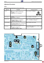
1. AM IF
2. AM Oscillator
3. AM Band Pass
4. FM Demodulator
5. 19kHz Filter
AM
;
Sweep Generator 450kHz
to
AM Aerial Input
;
Ue > 60dB
µ
V;
Oscilloscope
via 100nF to
Testpoint
A
.
AM
,
522kHz
;
Digital Voltmeter
to
Testpoint
B
.
AM
;
Couple
Signal Generator
via
Loop Antennas
;
Ue > 50dB
µ
V; f
mod
= 1kHz;
Oscilloscope
to
Loudspreaker Output
.
FM
;
Signal Generator with exact frequency to FM Aerial Input
(alternatively: Radio Station).
Digital Voltmeter
between
Testpoints
D
and
E
.
FM
;
Signal Generator to FM Aerial Input;
Ue = 50dB
µ
V; f
mod
= 19kHz;
Oscilloscope
to
Loudspreaker Outputs
.
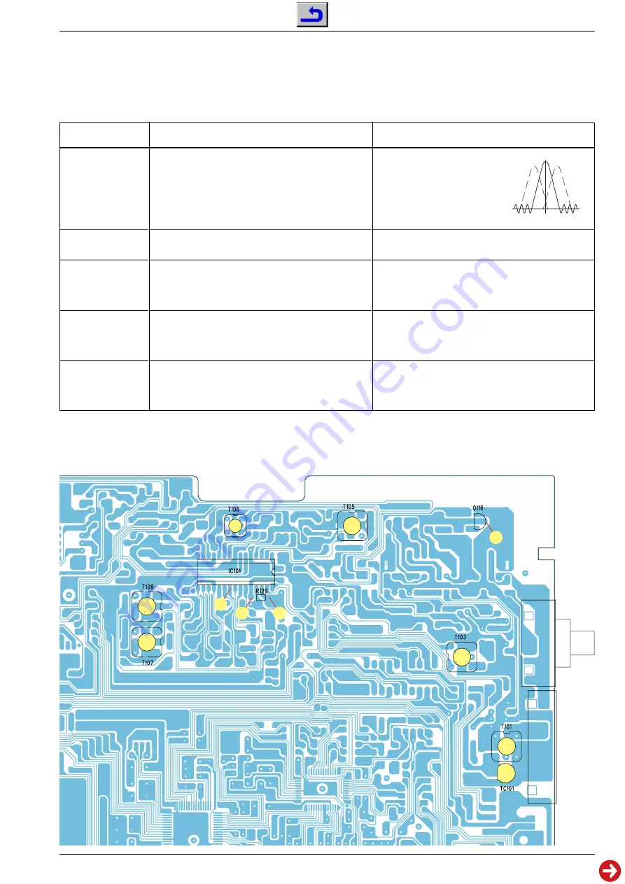
Adjust with
T105
a
for
Maximum
.
Adjust with
T103
b
for
1.7V
±
0.05V
.
Adjust alternating with
T101
c
at
603kHz
and with
TC101
d
at
1404kHz
for
AF Maximum
.
Adjust with
T106
e
for
0V
±
0.04V
.
Adjust with
T107
g
(
left channel
) and with
T108
f
(
right
channel)
for
AF Minimum
.
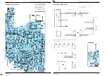
a
b
c
d
e
g
f
A
E
D
B

