GRUNDIG Service
UMS 4710 DEC
1 -
Technische Daten
Dieses Gerät ist funkentstört entsprechend den geltenden EU-Richtli-
nien. Es erfüllt die europäischen Richtlinien 2006/95/EC, 2004/108/EC,
1999/5/EG und entspricht der Sicherheitsbestimmung DIN EN 60065
(VDE0860) und somit der internationalen Sicherheitsvorschrift IEC
60065.
System
Spannungsversorgung:
Betriebsspannung.................................................................... 230V~
Netzfrequenz ........................................................................ 50/60Hz
Max. Leistungsaufnahme ........................................................... 45W
Leistungsaufnahme in Stand-by .................................................
≤
2W
Verstärkerteil
Ausgangsleistung:
Sinusleistung ...........................................................................2 x 5W
Musikleistung ...........................................................................2 x 8W
Empfangsteil
Empfangsbereich:
FM .......................................................................... 87,5 ...108,0MHz
MW ............................................................................522 ... 1620kHz
CD Teil
Frequenzgang ............................................................ 20Hz ... 20kHz
Geräuschspannungsabstand (wtd.).........................................
≥
68dB
MP3-Features
Ordner und Titel...... Max. 999 Titel einschließlich Anzahl der Ordner
File System/File Management ..............ISO 9660 Level 1 kompatibel
USB
USB 1.1 .............................................. kompatibel für Format FAT 32
Abmessungen und Gewicht
Abmessungen Gerät B x H x T ........................... 165 x 242 x 205mm
Gewicht Gerät.......................................................................... 2,68kg
Abmessungen Lautsprecher B x H x T ............... 145 x 242 x 155mm
Gewicht Lautsprecher.............................................................. 1,74kg
Technical data
This device is noise-suppressed according to the applicable EU direc-
tives. It fulfils the European directives 2006/95/EC, 2004/108/EC and
1999/5/EC and conforms to the safety regulation DIN EN 60065 (VDE
0860) and therefore the international safety regulation IEC 60065.
System
Power supply:
Operating voltage .................................................................... 230V~
Mains frequency ................................................................... 50/60Hz
Max. power consumption............................................................ 45W
Power consumption in standby...................................................
≤
2W
Amplifier unit
Output:
Sine wave power .....................................................................2 x 5W
Audio power.............................................................................2 x 8W
Receiver unit
Reception range:
FM ......................................................................... 87.5 ... 108.0MHz
MW ...........................................................................522 ... 1,620kHz
CD unit
Frequency response ................................................... 20Hz ... 20kHz
Noise voltage ratio (wtd.) .........................................................
≥
68dB
MP3 features
Folder and track............. max. 999 tracks, including number of folder
File system/file management ................ISO 9660 Level 1 compatible
USB
USB 1.1 ................................................ compatible for format FAT32
Dimensions and weight
Device dimensions W x H x D ............................ 165 x 242 x 205mm
Device weight .......................................................................... 2.68kg
Loudspeaker dimensions W x H x D .................. 145 x 242 x 155mm
Loudspeaker weight ................................................................ 1.74kg
Servicehinweise
Achtung: ESD-Vorschriften beachten
Vor Öffnen des Gehäuses Netzstecker ziehen.
CD-Laufwerk
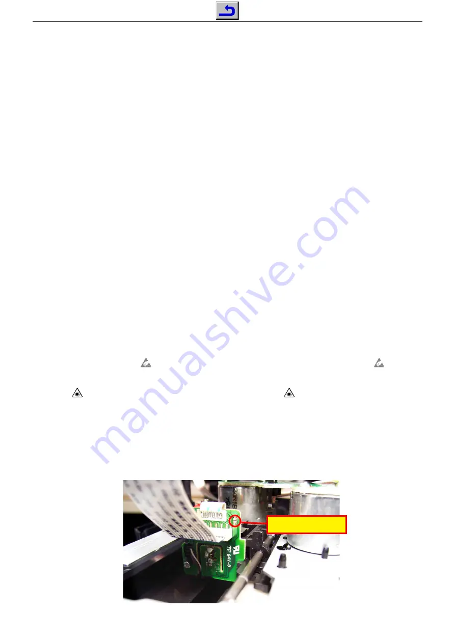
Bei Ausbau der Lasereinheit oder der Servo-Leiterplatte muß vor
Abziehen der Steckverbindung eine Schutzlötstelle auf der Leiter-
platte der Lasereinheit angebracht werden, um eine Zerstörung der
Laserdioden durch statische Aufladung zu vermeiden.
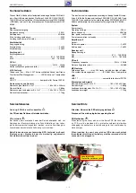
Beim Einbau einer neuen Lasereinheit (CD-Laufwerk) muß nach
Einstecken der Steckverbinder die werkseitig angebrachte
Schutzlötstelle entfernt werden!
Service Hints
Attention: Observe the ESD safety regulations
Disconnect the mains plug before opening the set.
CD Mechanism
When removing the Laser pick-up or the Servo PCB, the Laser pick-
up PCB must be provided with a protective soldered joint before
unplugging the connectors to avoid damage to the Laser diodes by
static charges.
When inserting the new Laser pick-up (CD drive mechanism)
the soldered joint fitted at the factory must be removed after the
connectors are plugged in.
Schutzlötstelle
Protective soldered joint
Summary of Contents for UMS 4710 DEC
Page 5: ...GRUNDIG Service UMS 4710 DEC 1...
Page 6: ...GRUNDIG Service UMS 4710 DEC 1...
Page 7: ...GRUNDIG Service UMS 4710 DEC 1...
Page 8: ...GRUNDIG Service UMS 4710 DEC 1...
Page 9: ...GRUNDIG Service UMS 4710 DEC 1...
Page 11: ...GRUNDIG Service UMS 4710 DEC 1 11...
Page 12: ...GRUNDIG Service UMS 4710 DEC 1 12...
Page 13: ...GRUNDIG Service UMS 4710 DEC 1 13...
Page 14: ...GRUNDIG Service UMS 4710 DEC 1 14...
Page 15: ...GRUNDIG Service UMS 4710 DEC 1 15...
Page 20: ...GRUNDIG Service UMS 4710 DEC 2 Hauptplatte Main PCB Sicht auf L tseite View on Solder Side...
Page 25: ...GRUNDIG Service UMS 4710 DEC 2 Displayplatte Display PCB...
Page 28: ...GRUNDIG Service UMS 4710 DEC 2 12 USB SD Anschl sse USB SD Connectors...


