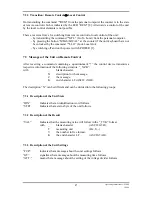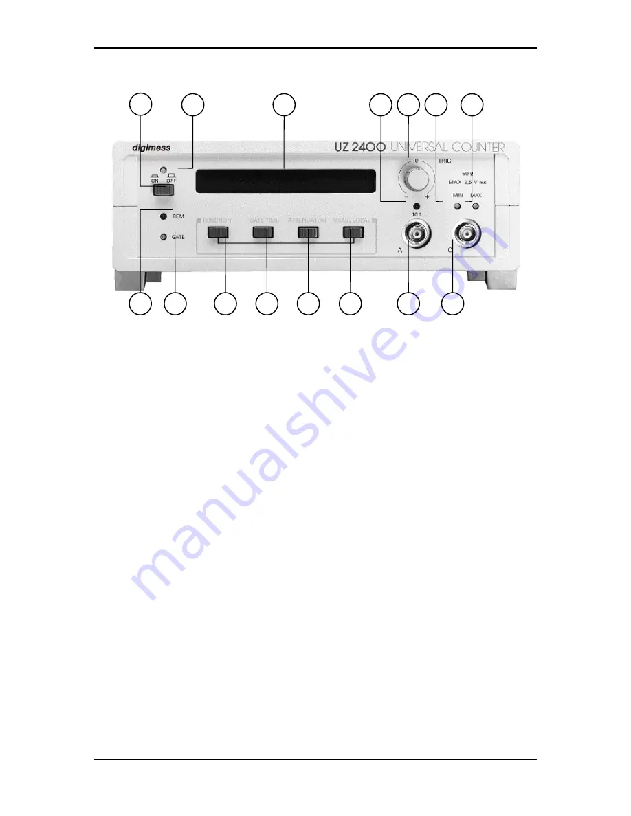
5 Control Elements
10
11
12
15
14
8
3
4
5
6
7
13
9
1 2
(1)
Power switch
(2)
Control indication
The LED indicates whether the unit is ready for operation.
(3) C
ontrol indication “GATE”
The LED lights up during the measuring time (GATE TIME).
(4)
“FUNCTION” button
After switching on the function “CHK” (function control) is automatically set.
Via repeated actuating of the button “FUNCTION” the following functions are
selected and displayed:
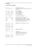
“FRA” (frequency measurement: channel A),
“FRC” (frequency measurement: channel C),
“PER” (period length measurement: channel A),
“TOT” (simple pulse counting: channel A),
“CHK” and so on.
(5)
“GATE TIME” button
The repeated actuating of this button allows the setting of the measuring times 10 µs,
100 µs, 1 ms, 10 ms, 100 ms, 1 s, 10 s and is displayed as follows:
“Gate time: 10 µs (100 µs, 1 ms, 10 ms, 100 ms, 1 s, 10 s)”.
(6)
“ATTENUATOR” button
The button “ATTENUATOR” is used to set the input voltage ratio to “1:1” or “10:1”
on channel A.
12
Operating Instructions UZ 2400
1/2000


