GRUNDIG Service
VARIXX UMS 4800
2 - 2
Adjustment Procedures
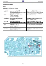
Tuner
Test equipment: Signal Generator, Sweep Generator, Oscilloscope
Adjustment
Preparation
Adjustment Procedure
1. MW Oscillator
2. AM IF
3. MW Pre Stage
4. FM Oscillator
5. FM IF
6. FM Pre Stage
Set the tuning knob to it´s left limit stop.
Set the tuning knob to it´s right limit stop.
Couple Sweep Generator via Loop Antenna.
f = 450kHz; no modulation;
short circuit T204 by a 100nF capacitor.
Oscilloscope to IC201-(19).
Couple Signal Generator via Loop Antenna.
30% modulation
Oscilloscope to AF Output.
Set the tuning knob to it´s left limit stop.
Set the tuning knob to it´s right limit stop.
Sweep Generator to IC201-(22).
f = 10.7MHz; no modulation;
short circuit L203 by a 100nF capacitor.
Oscilloscope to IC201-(19).
Signal Generator to antenna input;
Ue ~ 25dB
µ
V; f
mod
= 1kHz; deviation = 22.5kHz;
Oscilloscope to AF Output.
Adjust display frequency indication to 522kHz with T204.
Adjust display frequency indication to 1620kHz with
PVC201c.
Adjust T202 for Maximum.
Adjust alternating with T201 at 612kHz and PVC201d at
1404kHz for maximum.
Adjust display frequency indication to 87.5MHz with L203.
Adjust display frequency indication to 108MHz with
PVC201b .
Adjust alternating with T205 and T203 for maximum and
symmetry.
Adjust alternating with L202 (bend) at 90.0MHz and
PVC201a 106.0MHz for maximum.


