GRUNDIG Service
Chassis LX
1 -
Table of Contents
Page
General Section .................................. 1-2…1-18
General Notes ...............................................................................1-2
Product and Display Variants .........................................................1-3
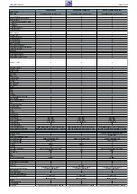
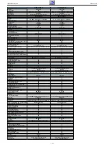
Technical Data ...............................................................................1-4
Operating Hints ............................................................................1-12
Service and Special Functions ....................................................1-15
Layout of the PCBs
and Circuit Diagrams ......................... 2-1…2-32
Main Board ....................................................................................2-1
– Power Supply ..........................................................................2-10
– IN/OUT 1..................................................................................2-11
– IN/OUT 2..................................................................................2-12
– IN/OUT 3..................................................................................2-13
– Amplifier ...................................................................................2-14
– Tuner ........................................................................................2-15
– COFDM Demodulator ..............................................................2-16
– Scaler.......................................................................................2-17
– Overview ..................................................................................2-19
Power Supply Board Z4J194 .......................................................2-20
Power Supply Board XLA194 ......................................................2-23
Power Supply / Inverter Board FSP060-2L02A ...........................2-26
Keyboards ACE191, XGE191 / XGJ191, Z9S191, ZP3191 ........2-28
Keyboard ZV6191
ZV6191 ........................................................................2-29
ZP3195, XDL192 ......................................2-29
LED Boards X7A192, ZP3193 / Z8K193, ZV7193.......................2-30
Headphone Board 8�9198
8�9198 ..........................................................2-30
Socket Boards XDJ197, XFA197 .................................................2-3
Socket Boards XGA193, ZV5197 ................................................2-32
Spare Parts Lists .................................. 3-1…3-9
Inhaltsverzeichnis
Seite
Allgemeiner Teil .................................. 1-2…1-18
Allgemeine Hinweise .....................................................................1-2
Geräte- und Display-Varianten ......................................................1-3
Technische Daten ..........................................................................1-4
Bedienhinweise ...........................................................................1-10
Service- und Sonderfunktionen ...................................................1-15
Platinenabbildungen
und Schaltpläne .................................. 2-1…2-32
Hauptplatte ....................................................................................2-1
– Netzteil ....................................................................................2-10
– IN/OUT 1..................................................................................2-11
– IN/OUT 2..................................................................................2-12
– IN/OUT 3..................................................................................2-13
– Verstärker .................................................................................2-14
– Tuner ........................................................................................2-15
– COFDM Demodulator ..............................................................2-16
– Scaler.......................................................................................2-17
– Übersicht..................................................................................2-19
Netzteil-Platte Z1J194 .................................................................2-20
Netzteil-Platte XLA194 ................................................................2-23
Netzteil-/Inverter-Platte FSP060-2L02A ......................................2-26
Keyboards ACE191, XGE191 / XGJ191, Z9S191, ZP3191
ACE191, XGE191 / XGJ191, Z9S191, ZP3191 ........2-28
ZV6191 ........................................................................2-29
DC-Eingangs-Platte XLA197 .......................................................2-29
Netzschalterplatten ZP3195, XDL192 .........................................2-29
LED-Platten X7A192, ZP3193 / Z8K193, ZV7193
X7A192, ZP3193 / Z8K193, ZV7193.......................2-30
Kopfhörerplatte 8�9198 ..............................................................2-30
Buchsenplatten XDJ197, XFA197
XDJ197, XFA197 ...............................................2-31
Buchsenplatten XGA193, ZV5197...............................................2-32
Ersatzteillisten ...................................... 3-1…3-9
General Section
General Notes
Before opening the cabinet disconnect the mains plug!
Attention: Observe the ESD safety regulations
Wiring
Before disconnecting any leads and especially the earth connecting
leads observe the way they are routed to the individual assemblies.
On completion of the repairs the leads must be laid out as originally
fitted at the factory to avoid later failures or disturbances.
Carrying out Measurements
When making measurements on semi-conductors with an oscilloscope,
ensure that the test probe is set to 10:1 dividing factor. If the previous
measurement was made on AC input, please note that the coupling
capacitor in the oscilloscope will be charged. Discharge via the item
being checked can damage the components.
Measured Values and Oscillograms
The measured values given in the circuit diagrams and oscillograms
are approximates!
Change of the Chassis Board
After changing the chassis board all settings in the service mode must
be done according to the table "Basic Settings" (point 1 in chapter
"Service and Special Functions" on page 1-15).
Allgemeiner Teil
Allgemeine Hinweise
Vor dem Öffnen des Gehäuses den Netzstecker ziehen!
Achtung: ESD-Vorschriften beachten
Leitungsverlegung
Bevor Sie die Leitungen und insbesondere die Masseleitungen lösen,
muss die Leitungsverlegung zu den einzelnen Baugruppen beachtet
werden.
Nach erfolgter �eparatur ist es notwendig, die Leitungsführung wieder
in den werkseitigen Zustand zu versetzen um evtl. spätere Ausfälle
oder Störungen zu vermeiden.
Durchführen von Messungen
Bei Messungen mit dem Oszilloskop an Halbleitern sollten Sie nur
Tastköpfe mit 10:1 - Teiler verwenden. Außerdem ist zu beachten, dass
nach vorheriger Messung mit AC-Kopplung der Koppelkondensator
des Oszilloskops aufgeladen sein kann. Durch die Entladung über das
Messobjekt können Bauteile beschädigt werden.
Messwerte und Oszillogramme
Bei den in den Schaltplänen und Oszillogrammen angegebenen
Messwerten handelt es sich um Näherungswerte!
Austausch der Chassisplatte
Nach Austausch der Chassisplatte müssen alle Einstellungen im Service
Mode nach Tabelle "Grundeinstellwerte" (Punkt 1 im Kapitel "Service-
und Sonderfunktionen" auf Seite 1-15) eingestellt werden.
Summary of Contents for Vision 6
Page 11: ...Chassis LX GRUNDIG Service 1 11 ...
Page 13: ...Chassis LX GRUNDIG Service 1 13 ...
Page 14: ...Chassis LX GRUNDIG Service 1 14 ...
Page 29: ...GRUNDIG Service Chassis LX 2 11 Hauptplatte Main Board IN OUT 1 ...
Page 30: ...GRUNDIG Service Chassis LX 2 12 Hauptplatte Main Board IN OUT 2 ...
Page 31: ...GRUNDIG Service Chassis LX 2 13 Hauptplatte Main Board IN OUT 3 ...
Page 34: ...GRUNDIG Service Chassis LX 2 16 Hauptplatte Main Board COFDM Demodulator 8 9 ...
Page 35: ...GRUNDIG Service Chassis LX 2 17 Hauptplatte Main Board Scaler 2 3 4 5 6 0 ...
Page 36: ...GRUNDIG Service Chassis LX 2 18 Hauptplatte Main Board Scaler 3 4 ...


