background image


www.grupotemper.com                                                                                                          9          10                                                                                                          
www.grupotemper.com 

KPF-02 

OPERATING INSTRUCTIONAC CLAMP  METER 


KPF-02

OPERATING INSTRUCTIONAC CLAMP  METER

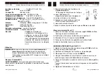
1. 

Insert the black test lead into the negative COM terminal and the 

 red test lead into the positive terminal. 

2. 

Set the function switch to the         •))) 

Ω

 position.                                                              

3. 

Use the multifunction MODE button to select resistance. 

4. 

Touch the test probe tips across the circuit or component under  

test. It is best to disconnect one side of the device under test so  
the rest of the circuit will not interfere with the resistance reading. 

5. 

For Resistance tests, read the resistance on the LCD display. 

6. 

For Continuity tests, if the resistance is < 100

Ω

, a tone will sound. 

 
Diode Measurements 

1. Insert the black test lead banana plug into the negative COM jack 

and the red test lead banana plug into the positive diode jack. 

2. Turn the rotary switch to the       •))) position. 

3. Press the MODE button until “     “ appears in the display. 

4. Touch the test probes to the diode under test. Forward voltage will 

indicate 0.4V to 0.7V. Reverse voltage will indicate “OL”. Shorted 
devices will indicate near 0mV and an open device will indicate 
OL” in both polarities. 


Capacitance Measurements 

WARNING: To avoid electric shock, disconnect power to the unit 
under test and discharge all capacitors before taking any 
capacitance measurements. Remove the batteries and unplug the 
line cords. 

1. Set the rotary function switch to the cap position. 
2. Insert the black test lead banana plug into the negative (COM) 

jack. 
Insert the red test lead banana plug into the positive (V)  jack. 

3. Touch the test leads to the capacitor to be tested. 
4. Read the capacitance value in the display 
Frequency or  % duty cycle measurements 

1.  Set the rotary function switch to the “Hz/%” position. 
2.  Insert the black lead banana plug into the negative COM jack 

and the red test lead banana plug into the positive V jack. 

3.  Select Hz or % duty with the Hz/% button. 
4.  Touch the test probe tips to the circuit under test. 

5.

  Read the frequency on the display.


Temperature Measurements 
WARNING: 
To avoid electric shock, disconnect both test probes 

from any source of voltage before making a temperature 
measurement. 

1. 

Set the function switch to TEMP. 

2. Insert 

the 

Temperature Probe into the negative (COM) and the 

V jacks, making sure to observe the correct polarity. 

3. Select 

°

C or 

°

F with the MODE button. 

4. 

Touch the Temperature Probe head to the part whose 

temperature you wish to measure. Keep the probe touching the part 
under test until the reading stabilizes (about 30 seconds). 

5. 

Read the temperature in the display. The digital reading will 

indicate the proper decimal point and value. 

WARNING:  To avoid electric shock, be sure the thermocouple has 
been removed before changing to another measurement function 

Data Hold 
To freeze the LCD meter reading, press the data hold button. The 
data hold button is located on the left side of the meter (top button). 
While data hold is active, the DH display icon appears on the LCD. 
Press the data hold button again to return to normal operation. 

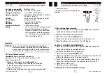
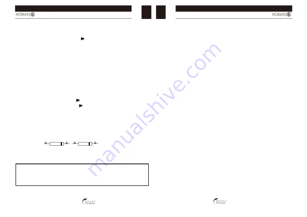
Red               Black     Black           Red 
Probe            Probe    Probe           Probe 

Forward test        Reverse test


Summary of Contents for Koban KPF-02

Page 1: ...No aplicar voltaje al mult metro cuando se encuentre en modo Resistencia Poner el conmutador rotativo en modo OFF cuando el mult metro no se est usando ADVERTENCIAS Antes de realizar la medici n situa...

Page 2: ...e sarse otros med no portan corrie cificaciones de na puede verse L mites de la Entrada m 400A 200mA 250 fusible de a 600V DC A 250V DC A 60V DC 24 KPF 02 TRO A PINZA e las puntas de to el mult metro...

Page 3: ...3 5 5 d gitos Capacidad 40 00nF 5 0 lectura 10 d gitos 400 0nF 3 0 lectura 5 d gitos 4 000 F 3 5 lectura 5 d gitos 40 00 F 100 0 F 5 0 lectura 5 d gitos Frecuencia 5 000Hz 1 5 lectura 5 d gitos 50 00H...

Page 4: ...h con picos etensi n inferio specificada en 7 8 a nal 0o C 0o C de I hogar ores la Func ADVE Med ADV punt desc realiz las m 1 Sit 4A desc pr supe di 2 Ap Cu La p Med 1 Co p 2 Sit 3 Se 4 Co 5 Le KPF 0...

Page 5: ...a punta de prueba negra macho en el terminal negativo COM y la punta roja macho en el conector positivo hembra Diodo 2 Situar el conmutador rotativo en la posici n 3 Presione el bot n MODE hasta que a...

Page 6: ...l icono DH en la pantalla Presionar el bot n de Retenci n de medida de nuevo para volver al estado normal de funcionamiento Nota Cuando la pantalla est retroiluminada la caracter stica de Retenci n de...

Page 7: ...o pin a quando a fun o de resist ncia estiver selecionada Mude o bot o de fun o para OFF quando n o estiver a utilizar o aparelho AVISOS Mude o bot o de fun o para a posi o apropriada antes da medi o...

Page 8: ...ricas o s varia es vem ser utiliza est o a funcion modo diferent lo equipamento Limites de entra Entrada 400A 200mA 2 r pida 600V CC 250V CC 60V CC KPF 02 M TRICA CA dos cabos de didor Repare o za o s...

Page 9: ...0 0 F 5 0 leitura 5 d gitos Frequ ncia 5 000Hz 1 5 leitura 5 d gitos 50 00Hz 1 2 leitura 2 d gitos Sensibilidade 5 5kHz 10Vrms 500 0Hz 5 000kHz min 5kHz 150kHz 40Vrms min ciclo de servi o 20 a 80 50 0...

Page 10: ...stados peracional ante de fun o par m uso 7 8 o C a goria s na s a 4 a se a n 2 Pr m u O co Med 1 I t 2 M 3 S 4 L 5 L Med 1 In e 2 Aj 3 Se 4 R po 5 En ci En do 6 Fo 7 Le KPF 02 INSTRU E 00 ou 40A Se l...

Page 11: ...choques el tricos desligue a alimenta o da unidade sob teste e descarregue todos os condensadores antes de proceder a qualquer medi o de capacidade Remova as baterias pilhas e os cabos de alimenta o 1...

Page 12: ...igada Volte a pressionar a tecla HOLD para sair deste modo Retroilumina o A fun o de retroilumina o ilumina o ecr e utilizada quando a luz ambiente demasiado fraca para permitir a visualiza o das leit...

Page 13: ...e tension sur le m tre lorsque la fonction de r sistance est s lectionn e R glez l interrupteur de fonction sur OFF lorsque le m tre n est pas utilis AVERTISSEMENTS R glez l interrupteur de fonction s...

Page 14: ...itude de c res moyens do sont pas sous mani re non sp r l quipement Limites d entr e Entr e Maxi 400A Fusible d 200mA 250V e 600V CC CA 250V CC CA 60V CC 24V KPF 02 E PINCE CA er la batterie me pour v...

Page 15: ...4 000 F 3 5 du r sultat 5 chiffres 40 00 F 100 0 F 5 0 du r sultat 5 chiffres Fr quence 5 000Hz 1 5 r sultats 5 chiffres 50 00Hz 1 2 r sultats 2 chiffres Sensibilit 5 5kHz 10Vrms min 5kHz 150kHz 40Vr...

Page 16: ...rie ez sit 1 R pl S conn p une 2 Ap p 3 se L cr Mes 1 Ins te 2 Po 3 Ch 4 Co 5 Lis MES 1 Ins test r 2 Po 3 Ch 4 Co po 5 To cir To cir 6 Ap KPF 02 INSTRUCTI glez l interrupt age400A ou 4 Si la plage de...

Page 17: ...aleur proche de et un appareil ouvert indiquera OL aux deux polarit s Mesures de capacit AVERTISSEMENT Pour viter un lectrochoc d connectez l alimentation de l unit test e et d chargez tous les conden...

Page 18: ...on HOLD s activera lorsque le r tro clairage sera allum Appuyez de nouveau sur la touche HOLD pour quitter le mode R tro clairage La fonction de r tro clairage illumine l cran et est utilis e lorsque...

Page 19: ...fore measuring When measuring volts do not switch to current resistance modes Do not measure current on a circuit whose voltage exceeds 240V When changing ranges using the selector switch always disco...

Page 20: ...ance 250V DC 60V DC KPF 02 AMP METER rom the device r Continuity tes ult and mislead ecessed electric that the termin ed by the pment may be m Input 250V fast acting C AC C AC 24V AC 3 4 e sts ding ca...

Page 21: ...cy 5 000Hz 1 5 reading 5 digits 50 00Hz 1 2 reading 2 digits Sensitivity 5 5kHz 10Vrms 500 0Hz 5 000kHz min 5kHz 150kHz 40Vrms min 20 to 80 duty cycle 50 00kHz 150 0kHz Duty Cycle 0 5 to 99 0 1 2 read...

Page 22: ...es g n accordance w ory II Pollution y II includes loc rtable equipme overvoltages le Cat III precaution of this operatio he function sele eter is not in us nt known ower e conductor 7 8 o C m with ca...

Page 23: ...t lead banana plug into the negative COM jack Insert the red test lead banana plug into the positive V jack 3 Touch the test leads to the capacitor to be tested 4 Read the capacitance value in the dis...

Page 24: ...he button a second time to turn the backlight off ZERO BUTTON For ACA and Capacitance Zero Offset adjustment Manual Ranging The meter turns on in the autoranging mode Press the Range button to go to m...

Reviews: