78
The diagram shows a typical application involving
a process start up, setpoint change and load distur-
bance. In each case, self-tune observes one complete
oscillation before calculating new terms. Successive
deviations cause the values to be recalculated con-
verging towards optimal control. When the controller
is switched off, these terms are stored and used as
starting values at switch on. The stored values may not
always be ideal, if for instance the controller is new or
the application has changed. In this case the user can
use pre-tune to establish new initial values for self-tune
to fine-tune.
Use of continuous self-tuning is not always appropri-
ate. For example frequent artificial load disturbances,
such as where an oven door is often left open for ex-
tended periods, might lead to calculation errors. In
standard control mode, PI & D are all calculated, which
may not suit all processes. Self-Tune cannot be en-
gaged if the instrument is set for on-off control or with
cascade control mode.
Manually Tuning
Tuning Control Loops - PID with Primary
Output only
This technique balances the need to reach setpoint
quickly, with the desire to limit setpoint overshoot at
start-up or during process changes. It determines val-
ues for the primary proportional band and the integral
and derivative time constants that allow the controller
to give acceptable results in most applications that use
a single control device.
This technique is suitable only for processes
that are not harmed by large fluctuations in the
process variable.
1. Check that the scaled input limits and the setpoint
limits are set to safe and appropriate levels for your
process. Adjust if required.
2. Set the setpoint to the normal operating value for
the process (or to a lower value if an overshoot be-
yond this value might cause damage).
3. Select On-Off control (i.e. set the primary propor-
tional band to zero).
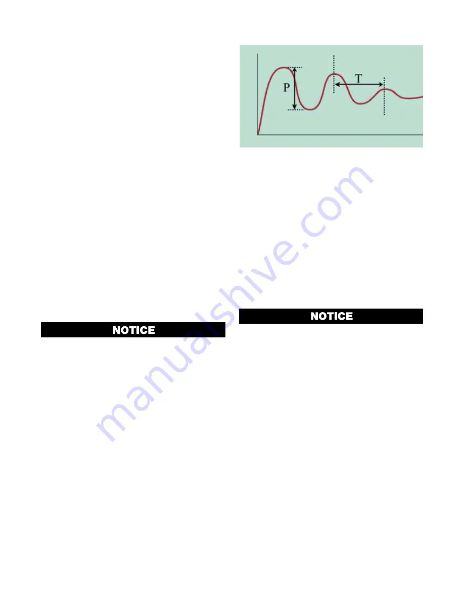
4. Switch on the process. The process variable will rise
above and then oscillate about the setpoint. Record
the peak-to-peak variation (
P) of the first cycle (i.e.
the difference between the highest value of the first
overshoot and the lowest value of the first under-
shoot), and the time period of the oscillation (
T) in
minutes. See the diagram below.
5. Calculate the PID control parameters (primary pro-
portional band, integral time and derivative time) us-
ing the formulas shown.
6. Repeat steps 1-5 for the second control loop if re-
quired.
Time
Pro
ce
ss
Va
riabl
e
Figure 60. Manually Tuning -
PID with Primary Output
P = Peak-to-Peak variation of first cycle
T = Time period of oscillation (minutes)
Primary Proportional Band =
P
Integral Time = T (minutes)
Dervitive Time = T/6
Tuning Control Loops - PID with Primary &
Secondary Outputs
This tuning technique balances the need to reach set-
point quickly, with the desire to limit setpoint overshoot
at start-up and during process changes. It determines
values for the primary & secondary proportional bands,
and the integral and derivative time constants that al-
low the controller to give acceptable results in most
applications using dual control (e.g. Heat & Cool).
These techniques are suitable only for pro-
cesses that are not harmed by large fluctua-
tions in the process variable.
Method 1 – For Simple Processes
Use this method if the process is simple/easily con-
trolled and the relative power available from the prima-
ry and secondary actuators is approximately symmetri-
cal (e.g. if the maximum heating and cooling power is
equal)
1. Tune the controller using only the Primary Control
output as described in steps 1 to 5 of Manually Tun-
ing - PID with Primary Output, above.
2. Set the Secondary Proportional Band to the same
value as the Primary Proportional Band and monitor
the operation of the controller in dual control mode.
3. If there is a tendency to oscillate as the control pass-
es into the Secondary Proportional Band, increase
its value. If the process appears to be over-damped
(slow to respond) in the region of the secondary
proportional band, decrease its value.
Summary of Contents for Chromalox 4081
Page 2: ...B ...


